|
My
Magnum Opus:
A Homebrewed Single Sideband Transceiver A comprehensive story containing historical, educational, technical and biographical elements & opinions by John Fuhring 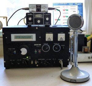 This is the technical, how the radio works, part of the story. Page 1 tells how I tell how I originally came to build my Magnum Opus. HOW
MY RADIO WORKS
Well, if you are still with me, let me start by
saying that this radio is actually very basic and simple and, except
for the
digital synthesizer, all the circuits are very old fashioned.
Back in
1917, Edwin Armstrong would have had no trouble understanding any of it
and he would have recognized that I used many of his inventions.
The primary principle that my radio is based on is
something that Armstrong discovered in 1917, that when you mix two
signals together (heterodyne them), multiple signals are produced.
Mixing gives you the original signals and, most importantly, you
get both a subtraction signal and
an addition signal. It is the addition or the subtraction signal
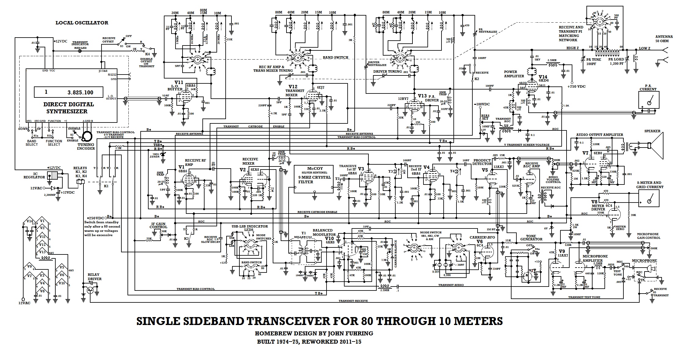
that makes the rest of the radio work. Here is an example of frequency mixing for using the radio on the 20 meter band: If you mix 5 megacycles (what we now call 5 MHz) and 14 megacycles together in a mixer tube, you get 5 + 14 = 19 MHz, but you also get 14 - 5 = 9 MHz. In my radio, the 5+14 is not important so it is rejected, but the 14-5 is very important and it is used. By the same token, 9 - 5 = 4 MHz (which isn't used), but 9 + 5 = 14 MHz and that is used to transmit my voice as you will see. Anyway, the important thing to know is that there are both high and low frequencys that are newly created when you mix two signals together and one of those products is very important to the radio. Let us begin with the receiver section of this radio, but before you start, I think that it would help if you downloaded the schematic diagram and print it out in as large a format as is practical for you. THE
RECEIVER SECTION
The receive section can be described as a "single
conversion superheterodyne" and, except in a few details, this is a
design that
would have been very familiar to radio engineers even as far back
as 1920, except that the audion and other early tubes available at that
time would not have supported my radio's design. Also, the use of
crystals as a filter would have been a novel idea at that time. To begin the discussion, let us assume that somebody is talking on a radio frequency of 14,000,000 cycles per second (called 14 million Hertz or 14 MHz). The 14 MHz signal travels through space and is picked up by my antenna where it causes a tiny, but high frequency voltage to appear. This tiny voltage goes through a matching network at the the upper left of the schematic diagram where the "low impedance" of the antenna is matched to the "high impedance" of the receiver's RF amplifier tube. 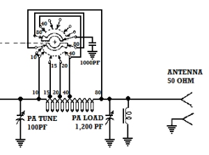 The signal from the antenna goes through the "Pi" matching network before going to the RF amplifier. After passing
through the matching network it goes through a relay that disconnects
this circuit while transmitting (when high voltage and power is
present) and then is wired to the input of the radio frequency
amplifier (RF amp).
The tiny
signal from the antenna is boosted in the RF amp, but is still pretty
tiny. The boosted
signal from the RF amplifier is then fed to pin 2 of the receiver mixer
( left side of V2).
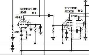 The signal appears on pin 1 of
the 6BA6 RF amplifier tube,
gets boosted and is then fed to pin 2 of the 6EA8 receiver mixer. The Local Oscillator (VFO) is a very important part of a superheterodyne radio, so here's what mine looks like now. 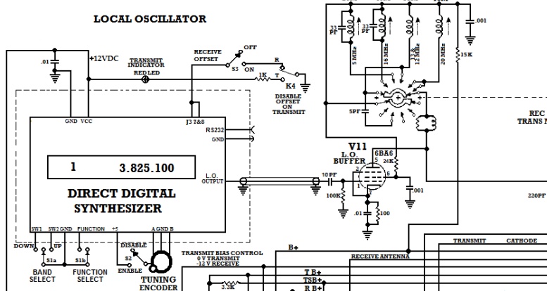 Originally my LO was a coil and tuning capacitor arrangement called a Hartley oscillator. This kind of LO worked well in radios for100 years, but they drifted terribly and now we have things much better using computer chips. I replaced the Hartley oscillator circuit with a Direct Digital Synthesizer (DDS) and rewired the V11 to serve as the LO's buffer and amplifier. In a sense, replacing the coil/capacitor LO with a DDS is the most important and useful modification that I have made to my old radio. I say that because my radio's low frequency drift and the accuracy of its frequency readout is as good as the best factory built radios. At this point, you may wonder why a LO is needed. As mentioned, this radio uses the "superheterodyne" principal and that means that a signal from the antenna is "heterodyned" or "mixed" with another signal that results in a third signal that can be filtered and amplified in a special stage called the Intermediate Frequency Amplifier Stage otherwise simply known as "the IF strip." Almost 100 years ago, the frequency of nearly all IF strips was set at 455 kilocycles (kHz) as a really good compromise of several factors. In my radio I am using a IF frequency that is almost 20 times higher (at 9 megacycles) so that I can take advantage of a very sharp crystal filter, but it still works on the very same principle. Before I continue, let me back up a bit and return to discussing a little more regarding the mixer stage with an actual example of a frequency being mixed to produce the IF to better illustrate how all this works. There in the receiver mixer's pentode section, the original 14 MHz signal from the antenna and the RF amplifier is mixed with a 5 MHz signal from the LO and a subtraction occurs. This subtraction produces the 9 MHz IF signal (14-5=9) and this 9 MHz signal has on it the voice information we want to listen to. We want the signal at 9 MHz because IF strip that follows after these circuits has a very sharp filter that is especially tuned to 9 MHz. This filter is so sharp that it only lets the audio we want to hear through and rejects most other audio and noise. By the way, my filter is a commercially made McCoy "Silver Sentinel" that I had mailed to me all those many years ago. It was designed and manufactured by experts to have a compact size and a level of performance that would have been very difficult for me to build into a home made filter. Earlier radios I built all had home made filters and they worked very well, but back then I decided that the McCoy filter was the best way to go for this project. 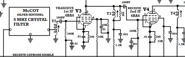 The problem with using a crystal filter is that it takes an already weak signal and weakens it further. To boost the signal back up and then boost it again, we use two stages of amplification called the first IF and the second IF amplifiers. By the time the signal gets boosted in the 2nd IF amplifier tube, it is at a usable voltage, but it is still at a radio frequency of 9 MHz, which can't be heard by the human ear and it is still a single side band signal. To convert the signal into something we can hear, further processing is necessary and that is done by the Product Detector and the Audio Amplifier stages. 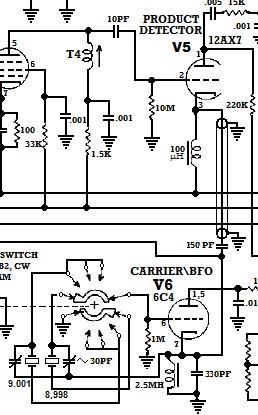 In this example, I have shown how one frequency (1,000 Hz) is detected, but detecting voice audio works on the very same principle. You know that a person's voice is just a series of varying frequencys or tones (some higher, some lower, some louder and some softer) and they demodulate the same way as a single tone does by "heterodyning" with the BFO to produce audio frequency signals. An old fashioned way of referring to this stage is to call it the "Second Detector" (with the "First Detector" being the stage (V2) that mixes the L.O. & the antenna signal from the RF amplifier to create the IF frequency). The Product Detector tube produces the audio we want to listen to, but this audio is very weak. This weak audio signal is then applied to two other circuits. One of the circuits that gets the audio is called the Automatic Gain Control (AGC). To produce an AGC signal, we need to boost up the audio signal by using the right half of V5 to amplify and then rectify whatever audio signal is present. This rectification process produces a negative DC voltage that is proportional to how much signal is there so that a strong signal will produce a lot of negative voltage and a weak signal will produce very little. The negative voltage that is produced appears on the AGC bus which is connected to the signal grids of the two IF amplifier tubes and because these tubes are "variable transconductance" tubes, this voltage will control how much they will amplify. So, a strong signal will produce a large negative AGC voltage and that will cause the IF tubes to amplify very little, but a weak signal will produce very little negative voltage and the IF tubes will amplify a lot. The end result is that both strong and weak signals sound about the same and the radio doesn't "blast your ears off" when you encounter a strong signal after listening to a weak signal. 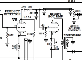 Audio from the product detector goes to the triode to its right where it is amplified. The plate of this tube is fed by the primary of a audio transformer with the secondary connected to a rectifier diode (lower right) that produces a negative AGC voltage that is proportional to the amount of audio present. The voice frequency signal from the product detector also goes to a volume control potentiometer (shown in the upper right of the above diagram) where I can set how loud I want my radio to play by turning the knob. The output from the potentiometer very weak so it is then amplified in the audio amplifier tube (V7) where it is boosted up to a level that can be heard in the loudspeaker. 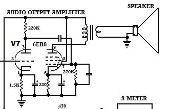 The weak audio from the volume control is boosted by the triode (left) section of V7 and then is further boosted by the power pentode (right) section for an output of up to 5 watts. Normally a beam tetrode tube would be used for power output, but I needed a dual tube with a triode pre-amplifier built into it. The 6EB8 performs both the input pre-amplifier and the power output functions with quite low distortion. That, in a nutshell, is how the receiver section of my radio works. THE
TRANSMITTER SECTION
The Transmitter section may also be thought of as
a superheterodyne only in reverse. Audio signals come in and are
"mixed" or heterodyned with other signals and finally built up to a
frequency that is then amplified and amplified again until they are
powerful enough to be sent to an antenna where they leave as
electromagnetic waves that can be heard thousands of miles away.
The whole process begins by me talking into a microphone. The microphone puts out an electrical signal that is then amplified by the microphone amplifier tube V9. 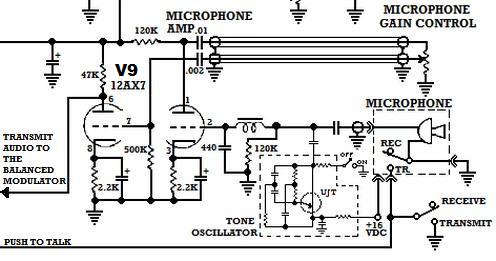 The
amplified voice is then mixed or heterodyned with the 9 megahertz
carrier/BFO oscillator (same one
used by the receiver's product detector) by the balanced modulator tube
V 10. This transforms my voice from an audio signal to a radio
frequency signal.
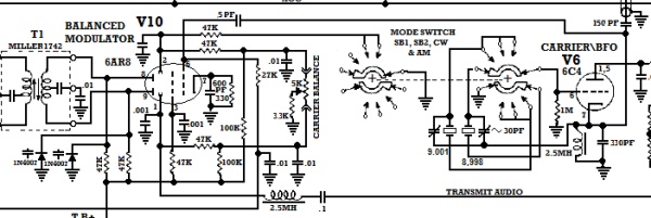 The balanced
modulator tube I'm using is a clever little tube originally developed
for color TV sets, but it works really well for this kind of thing too.
There are other ways to do the very same thing using old
fashioned triode
tubes, but a necessary balance wouldn't be so easy
to achieve. What this circuit does is balance out the carrier
frequency so that the Miller 1742 transformer (shown above) puts out
what's known as a "double sideband, suppressed carrier" signal.
What is a carrier and why is it important to suppress it? Well, you know that whenever an audio frequency is heterodyned (or mixed) with a radio frequency (like the 9 MHz BFO oscillator) you get three frequencies -- the product of addition, the product of subtraction and the original radio frequency. The original radio frequency is especially large and it is needed only if you wish to transmit old fashioned AM radio. For single side band (SSB) radio, the carrier needs to be eliminated. Anyway, here we are with a double sideband signal with my voice on both sidebands, but at least I've eliminated the carrier. Of course, I need to get rid of one of those sidebands and keep the other one. Unless one of the sidebands is eliminated, I'll be transmitting a double side band signal and half my transmitter power will be wasted. What I need to do next is "filter" out one of the sidebands and that's where the extra sharpness of the crystal filter comes in. 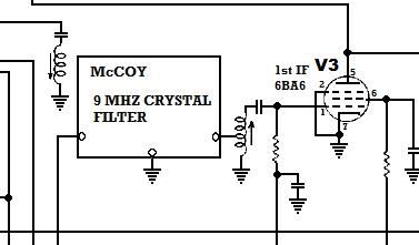 If this looks
familiar, it should because it is the same crystal filter and first IF
amplifier tube that is used in the receiver section. The double
sideband signal goes through the crystal filter which is so narrow that
one of the sidebands gets shaved off leaving only a single sideband
signal at 9 MHz. Again, some of the signal strength is lost going
through the crystal filter, but that loss is more than made up for by
the IF amplifier tube V3.
My voice is now a single sideband radio frequency signal, but it is only at 9 MHz. It needs to be at 14 MHz if I want anybody to hear me. To get my signal up to 14 MHz, I need to "mix" it with a 5 MHz signal from that same very important part of the radio called the Local Oscillator (also known as the VFO ) that I mentioned in the receiver section of this article. As I mentioned, the local oscillator creates a high frequency signal that is mixed with the 9 MHz signal that carries my voice. 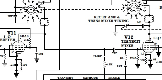 Let me repeat, the 9MHz signal from the crystal filter and IF amplifier is mixed with the same 5 MHz signal from the L.O. amplifier tube (V11) that is used in the receive section, but this time, the 5 MHz signal mixes in an additive way in the transmit mixer tube (V12) to produce the transmit frequency (9+5=14). As a technical aside, notice that V12 is a pentode. Normally a pentagrid converter type tube is used for a mixer, but in this case the signals from the L.O. amplifier and from the IF amplifier are at a pretty high level and putting both signals on pin 2 is a pretty good, low noise way of mixing the frequencies to produce 14 MHz. The 14 MHz signal produced by the transmit mixer tube is now the right frequency and it carries my voice on just one sideband as I want it to, but this signal is now very weak, at just a few milliwatts. Being so tiny, the signal is way, way, way too weak to transmit over the air and wouldn't be heard very far away. To boost the signal way up, the signal is fed to the power amplifier driver tube (V13). This is another pentode tube, but it is designed to handle more power. 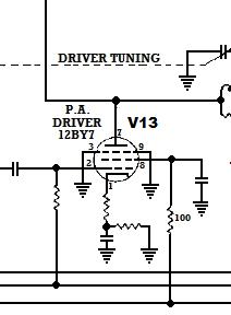
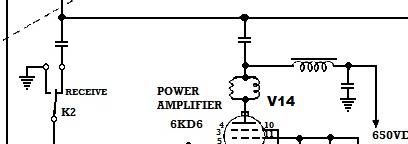
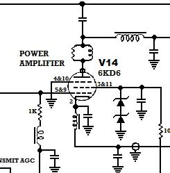
Transmit AGC circuit showing the Bias setting potentiometer, the 10 MF audio bypass capacitor, the grid current transformer and the negative AGC voltage rectifier diode. By the way, you might notice the 10MF capacitor to the left of the audio transformer. This is an audio bypass capacitor that is necessary for the transformer to function properly. In my original design, this capacitor was too small and the transmit AGC didn't work and that's why my radio would burst into self-oscillation. I spent untold hours trying to figure this out, but the problem was solved when I changing to a higher value of bypass capacitor. I wish all difficult and long term problems could be solved so simply. The my 6KD6 tube operates at nearly 700 volts and draws about 200 milliamps on voice peaks. A circuit with voltages and currents of this level operates at what they call a "high impedance level" so the tube can't be directly connected to an antenna because an antenna circuit is characterized by "low impedance." The powerful signal from this tube therefore must go through the same matching network I started the receiver discussion with, only in reverse. In this case, the signal "travels" from left the right. As you can see, the matching network works both ways, low impedance to high impedance if going from right to left and high impedance to low impedance if going from left to right. In other words, a signal from the antenna can be matched with the input to the receiver's RF amplifier going one way and a signal from the power amplifier tube can be matched to the antenna going the other way. .
My "Pi" Matching Network with the high impedance 6KD6 tube to the left (not shown) and the low impedance (typically around 50 ohms) antenna to the right. As I mentioned
in the receiver
section, there is a relay (K2) that disconnects this circuit from the
receiver's RF amplifier while the power amplifier is transmitting.
Without the relay blocking the signal during transmit,
the high power signal from the 6KD6 tube would melt the grid of the RF
amplifier tube and ruin it.
 K2 relay shown in the "receive" mode. The relay disconnects and switches the RF amplifier's input to ground while V15 is transmitting. This then, in
another nutshell, is how the transmitter section works. Of course
there are many supporting circuits that I haven't mentioned, but
perhaps if you study the schematic you will figure out what they are
and how they work.
Some of the supporting circuits include: A S-meter amplifier tube, a plate current meter circuit, an audio test oscillator, interstage tuning coils, transmit/receive relay control and a few others too. The
End
Having arrived this far,
obviously you have a superior attention span and reading ability that
far exceeds that of the
majority of web users. I highly value the opinion of people such as yourself, so I ask you to briefly tell me: Did
you enjoy this article
or were you disappointed?
If you have any detailed comments, questions, complaints or suggestions, I would be grateful if you would please
E-mail me directly If you didn't start at page 1, perhaps you will be interested to know how I came to build my radio back in the 1970s. If so, Please go to Page 1 of this story. I have a lot of other related things you might be interested in.  or, for something entirely different, Return to my Home Page |