A note before getting into the crystal radio story.
After I
experimented with the Heathkit CR1 crystal radio and built the radio
described below, I got out my old regenerative radio I made in 1958 and
was once again astounded by how much better it performed than even the
CR1. I have now come to the conclusion that anybody who wants to
build an ultra-simple radio really should consider my Armstrong
"Crystal" Radio first.
A miniature, but
selective and high performance
If you are determined to build a tiny crystal radio with no amplification or are just interested in reading about my crystal radio and how I built it for its entertainment and especially for its educational value, please read on. CRYSTAL RADIO KIT The description of a project intended for advanced science students and hobbyists and containing personal and controversial opinions and thoughts that you can skip by John Fuhring 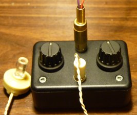 My tiny, but selective and sensitive crystal radio. Introduction Not long ago I
rebuilt and put into operation a Heathkit CR1 crystal radio. I
hadn't built a crystal radio since I put together my first radio when I
was 10 years old, nor had I used a crystal set since I was 13.
During the period of the mid to late 1950s, I owned at least
three crystal radios of varying performance. With the
Heathkit, I now had a crystal radio that performed far better than
any of the radios that I remember using as a kid and once again I
was struck by the magic of building and operating such an utterly
simple and basic radio receiver. Suddenly it occurred to me that it
might be fun to try my hand at designing and building my own crystal set from scratch.
Besides that, a former
grammar school
teacher I'm friends with suggested to me that school aged kids would have a lot of
fun learning about radio theory if they could build a working crystal
radio and he asked me to come up with such a radio.. Of course, this strongly reminded me of how, in 1955,
my aunt gave me crystal radio kit to build and how that experience lead to
my lifelong
interest in radio and my career in electronics. The memories flooded back and awoke in me that desire I think
we all have and that is to pass along to others those things that have helped us.
Well, I have given a lot of thought to crystal radios lately and I have concluded that the ultra-simple, very poorly performing crystal radios that most teachers have their classes construct are just not worth building. Rather than try to force kids who are just not interested in how their technological world actually works -- and after all, most of us only want to use technology, not design or even understand it -- I think that building a crystal set should be limited to only those students who show a genuine interest in this sort of thing. In my opinion, the only students who should build something like this are the kids I call a school's "the scientific elite" (but who others would call "the nerds"). I think that building a crystal radio should be done as an individual science project, but not as a class project. However, and this is most important, any radio anybody builds should be worth building and should at least approach the performance of the Heathkit CR1. It soon became my goal to design a low cost, but good performing little radio that would not only be easy and practical to build, but would be something a young person would be proud of and want to keep and use. Of course, this applies to adults too, even old geezers like me. So, the following paragraphs will describe the little radio I have come up with. Please be aware that because the little radio is very compact, it requires some very careful, precision soldering using a dangerously hot soldering iron. Additionally, winding 7 feet of wire on each of two toroid forms is tedious and requires manual dexterity and skill. Because of these difficulties, I am very much of the opinion that this little radio is not a project for very young (under 12) kids. You must use your own judgment regarding whether or not this project is practical for you or your student(s) to build.
Design
considerations for a simple but good performing crystal radio
Before I begin the technical phase of this article,
please note that I performed several experiments with different kinds
of wire and different detectors before I finalized the design that I
will be presenting. What I'm presenting here is how and with what
materials and components I think a builder should use for optimum
performance. Here then are my design criteria: Any crystal radio worth building should have good selectivity. That means that you should be able to hear a station without the audio of an adjacent station in there too. Of course, the selectivity of any crystal radio is such that, if you listen closely, you will always hear a powerful nearby station in with your station, but that unwanted signal should be very faint. Any crystal radio worth building should have good sensitivity. That means that you should be able to hear even relatively distant and weak stations. Of course, crystal radios have no amplification and depend entirely on capturing enough radio energy to operate the earphone to produce sound waves. The radio must have efficient tuning coils, tuning condensers and a efficient detector so that the tiny amounts of energy that is picked up by the antenna is not wasted or lost in the radio any more than absolutely necessary. If the radio is designed properly with low-loss components, the human ear, with its amazing ability to hear even very low energy sound waves, will do the rest. Any crystal radio worth building should be in a pleasing enclosure or chassis that makes mounting the components easy, makes connecting to the antenna and ground easy, makes it easy to plug in the earphones and makes operating the tuning controls convenient. When the project is complete, the builder should have a radio that looks like a radio and something (s)he is proud of and proud to show to others. Certainly, the Heathkit CR1 fits these criteria extremely well and I think that the little radio I will present on this page fits the criteria well too. In some respects, if I may say so myself, my radio fits some of them even better than the CR1. An update as of June 21, 2017
After exchanging some email with a reader, I have
revisited my little project and have rethought some things. I
then went in and made some simple modifications and I am extremely
pleased with the results. The modifications work so well, I am
redrawing the schematics and the improved version of this radio is what
I will present.Building the radio
List of parts:
1) Two each, T80-15 toroid cores. **2) Two each, dual section 335 X 335 PF variable tuning capacitors (670 PF total each). *** 3) Two each, knob and shaft extension for the above tuning capacitors. 4) Four each, 2.5 X 5 MM countersink screws to mount the tuning capacitors. 5) One 1N34A diode. 6) One piezoelectric earphone (or high Z magnetic earphones) with a miniature phone plug. 7) One panel mount miniature phone jack (to match item 6 above). 8) One, panel mount RCA type jack. 9) One RCA type plug with item 10 wire leads soldered to it to match item 8 above. 10) Two each, 6" 20 Ga. colored (red & black) insulated wire leads for the antenna and ground. (Use black for ground) 11) Two each, small alligator clips. Solder to the end of the above insulated wires for antenna and ground connections. 12) Two pieces of 40/46 litz wire each 7 feet long. No. 30 (or larger) magnet wire can be used but not recommended. 13) One 6" section No. 24 ga magnet wire for the interconnecting link. Litz wire can be used, but stiffer wire may be preferred. 14) One 24,000 ohm (24K) resistor. A 1/4 or 1/8 watt resistor is recommended to more easily fit in the limited space. 15) One L1 coil made of 6 turns of litz wire wrapped around a wooden match stick. Cut off unused wood. 16) One 12 coil made of 12 turns of litz wire wrapped around a wooden match stick. Cut off unused wood. 17) A single pole double pole miniature switch. 18) A small tube of RTV type adhesive. Do not use an adhesive that becomes hard because you may want to change coils. 19) Metal or plastic box to mount the components. 20) Antenna 60 + feet or as long as practical and mounted as high up as practical. ** Use only toroids made with the -15 material. Other cores will greatly complicate winding and/or degrade performance. Smaller cores may be used, but the number of turns will have to be adjusted. *** You can use smaller values for finer tuning. For large chassis projects, conventional 360 PF air variable condensers are excellent and will probably give you higher 'Q' and lower signal losses. Ganging the two sections of the miniature condensers as I have done gives a greater tuning and antenna trim range. Since the tuning of a crystal radio is so broad, condensers ganged this way are still easy to adjust for maximum signal and minimum interference from stations off to the side. Total cost of parts will be about $25 -$30. 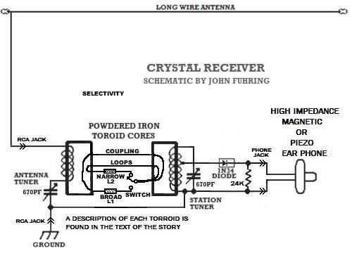
Suggest layout and
building instructions.
 All measurements are in inches. Steps in building the radio
First, shop around and pick out a suitable chassis box to put the radio in.
A small box such as shown above will accommodate the miniature
tuning condensers and the jacks for the earphone and antenna/ground RCA
jack, however the parts will be crowded as shown in the pictures.
A larger box will make assembly and soldering somewhat easier.
A plastic box will make drilling and mounting the components
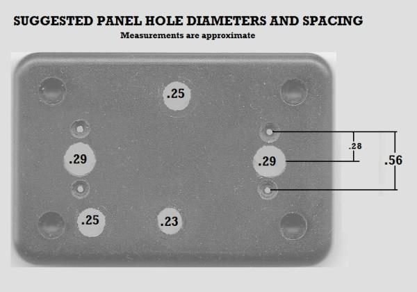
extremely easy. A small wooden box that could be lacquered and polished might be very handsome.The two capacitor extension shafts should be filed down for an overall length of 0.4 inches with the mounting screw cut to 0.48 inches. You can leave them their original length, but the knobs won't be flush with the panel. This radio uses two T80-15 toroid cores that are each wound with 7 feet of 40/46 litz wire. Three turns on each side form a coupling link between the toroids. The station tuner coil is tapped 30 turns from the top. At what will be the top of this coil and with an inch of wire sticking out, square knot tie the wire to the toroid (to hold it in place) and then begin winding the coil while counting each turn. At 30 turns, stop winding and create a tap. Tapping is accomplished by simply twisting the wire for about a half inch. Carefully start winding again and continue to wind until all the wire is used up (about 70 more turns). When finished winding, the twisted wire at the tap and the wires at the ends of the coils are heated with a soldering iron until the insulation melts and then "tin" the wires with hot solder. Note that the diagram that accompanies the tuning condensers shows which of the long metal tabs are connected to the stator (ground) and the rotor sides of the units. These condensers have 4 trimmers built into them, but we will not use any trimmers so ignore (or cut off) their tabs. With the photos and schematic as a guide, perform the following:
1) For the antenna tuning condenser, bend the rotor tabs over at a 90 degree angle and solder them together. 2) For the station tuning condenser, bend the rotor tabs over at a 90 degree angle and solder them together. 3) Extend the ground tabs (stators) of the two condensers until they touch and then solder them together. This is the ground bus. 4) Solder short pieces of bare wire from the outer shells of the RCA and phono jacks to this bus. 5) Trim the leads to fit and solder one side of the 24K resistor to this bus. 6) Place the other lead of the 24K resistor into the mounting hole of the ungrounded side of the phone jack. 7) Trim the leads of the detector diode to fit and place one lead in the same hole of the phone jack with the 24K resistor. 8) Solder the detector diode and 24K resistor leads from steps 6&7 to the phone jack. 9) Place the station tuning coil on top of the station tuning condenser and perform the following: 10) Solder the top of the station tuning coil to the station tuning condenser's rotor tabs. 11) Solder the bottom of the station tuning coil to the ground bus. 12) Place the antenna tuning coin on top of the antenna tuning condenser and perform the following: 13) Solder the top of the antenna coil to the ungrounded lug of the RCA jack. 14) Solder the bottom of the antenna coil to the rotors of the antenna tuning condenser. 15) Glue the two toroids to the tops of their tuning condensers as shown. Use a silicone rubber adhesive and allow it to set. 16) L1 With a 4 inch section of litz. wire, wind 6 turns on a wooden match stick and glue them down. Leave one end with a long pig-tail and the other end a little shorter. Trim off the excess wood. 17) L2 With a 4 inch section of litz. wire, wind 12 turns on a wooden match stick and glue them down. Leave one end with a long pig-tail and the other end a little shorter. Trim off the excess wood. 18) Solder the short end of L1 to the "wide" terminal of the switch. No stripping is necessary with litz wire. 19) Solder the short end of L2 to the "wide" terminal of the switch. No stripping is necessary with litz wire. 20) Thread the two L1 and L2 long wires through both toroids as shown and bring them out together to the center terminal of the switch. Twist them together and solder them on. Remove excess wire. 18) Solder the other side of the detector diode to the tap of the station tuning coil as shown. 19) Solder two 3-6 inch pigtail leads on to the RCA plug for the antenna (red) and ground (black) and solder alligator clips to their ends. 20) Connect the alligator clips to a long wire antenna and suitable ground, plug in the earphone and tune to a local station. Recheck wiring if you fail to detect a station. Refer to the schematic diagram and the photos below to make sure you have wired everything correctly. Remember that a schematic diagram is not exactly as a radio is wired, but is electrically correct and actual wiring must make all the connections (and no others) as shown. As long as the leads are kept short and if all the connections are made properly and there are no shorts to other parts of the circuit, the radio will work It is up to you to figure out the best routing and lead lengths for all the connections shown in the schematic. Keep in mind that external connections such as to the earphone, the antenna and the ground go to the earphone jack and the antenna jack respectively. If you are not familiar with schematic diagrams and how to wire something up using such a diagram, this is an excellent project for you to start learning how this is done. Finally, the RCA jack and the phono jack normally uses the outside shell connected to ground so that when they are bolted to a metal panel, they are at the right potential. If you are using an insulated panel to mount these jacks, it doesn't matter if the outside shell is grounded, but I recommended that you connect it this way. You may notice that the detector diode is shown in the schematic as "forward biased," however, it makes no difference (in this case only) which way you connect the diode. Tools you will need
1) A low wattage soldering
iron. A temperature controlled soldering station is ideal, but an
ordinary iron will
work fine. 2) A very fine needle nose plier or (better yet) a fine hemostat. 3) A small wire cutter. 4) Drill, bits and countersinking tool for cutting holes in the panel. 5) Screwdrivers to fit the various screws. 6) Pliers or wrenches for tightening the jack's mounting nuts. Do not over-tighten screws or nuts. Photos of the completed project in its tiny box
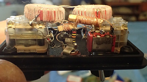 Plastic lid with all components mounted. The toroids are mounted with a drop of RTV. Silicone rubber mounts the toroids quite securely, but allows for future changes. Miniature tuning condensers have dual sections, each 335 PF and are ganged for 670 PF. The long ground tabs of the two condensers are soldered together and make a very convenient ground bus that the other components can attach to. Also shown here are L1 and L2 which are turns of litz wire wrapped on match sticks. This little radio will tune to the LF band below the broadcast band, but I doubt you will find anything down there to listen to. 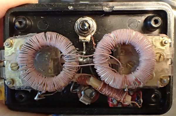 Looking down with the phone jack at the center bottom and the RCA antenna jack on the top. Notice a ground bus runs in the center connecting the two condensers and that the other components are soldered to it. 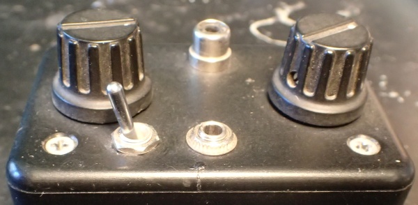 The front panel. Antenna tuning on the left, station tuning on the right. The toggle switch controls wide or narrow selectivity tuning. 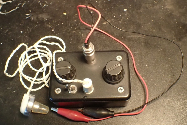 The completed project with a RCA plug attaching the antenna and ground. I think you will agree that this is a very neat little package. The tiny size belies its rather excellent performance. 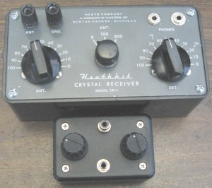 Here's a picture of both my radio and the Heathkit CR1 showing their relative sizes This is an old photo before the wide/narrow selectivity switch was installed. The
way this radio works is as basic as it is
possible to get
and here's how it all works:
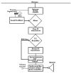
Here is a graphical
representation of what's going on when a
radio frequency signal is detected (turned into sound): 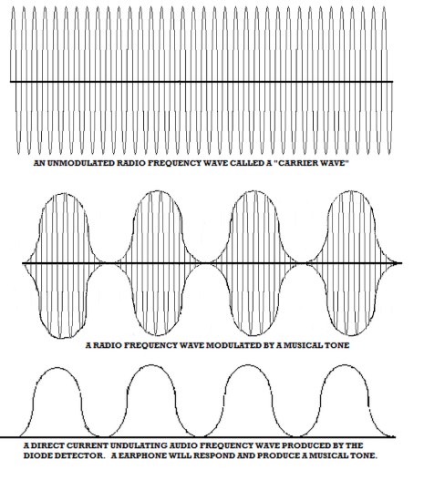
The
importance of a good antenna and ground system
These radios are not connected to your
house's AC
power and they use no batteries. A crystal radio has no
amplifying circuits and yet they output sound and sound is energy.
Where do they get the energy to make sound? Do they
somehow
use mysterious and occult "free energy from space" or
something
goofy like that? The energy needed to run these radios
doesn't
cost you anything directly, but it isn't free or mysterious.
The
energy is from a tiny fraction left over from the hundreds of watts of
radio frequency energy a station broadcasts out to space. The
vast, vast majority of the energy a broadcast station radiates out of
its antenna system is lost, but a tiny fraction of it may be picked up
by an antenna at somebody's house. Antennas for listening to AM stations can range from tiny "loop" antennas that are extremely inefficient, but good enough for amplified radios, all the way to elaborate "long wire" systems dozens and dozens of feet long and high up in the air. The general rule was discovered by Marconi over a hundred years ago that the longer and higher the antenna, the better it is at capturing some of that energy that is passing by. To capture enough passing energy so that it can be processed by the crystal radio's components and then come out as sound energy strong enough to vibrate the mechanism inside the earphone, the antenna needs to be as long and as high as is practical. Practical is what you have room for and how high you can safely go. Practical antennas can be strung between poles located at the ends of a roof or from the house out to a distant tree or pole. It is true that antennas longer than 60-100 feet and higher than 25 feet do capture more energy, but things soon get very difficult and for very little extra gain at distances and heights beyond what is practical. In addition to a really good long wire antenna (as long as is practical as mentioned), this radio must have a good ground. Right now, I am using my house's wiring as a ground and it seems to work well. Water pipes, when available to connect to, are supposed to work even better. When using house wiring, it would be a deadly mistake to connect to anything but the AC ground, so be careful. Tuning
this radio for maximum sensitivity and selectivity
The trick to tuning this radio is to
first locate a
strong local station of known frequency and tune it in with both the
antenna tuner and the station tuning controls. Both controls should be used
to
peak the signal for maximum loudness. Once you have an idea
where
on the dial your station is located, move both controls to about where
you guess the weaker station you want to listen to might be.
Once
there, slowly and carefully adjust the station tuning until you hear
something and then peak it up with the antenna tuning control.
You may have to go back and forth a few times to get maximum
volume with minimum interference from nearby and stronger stations.
The
best
time of the day to have fun with these kinds of radios
During the daytime and during the
summer months,
about all that can be received with a little set like this, at least
around here, is the trash in English that the local broadcasters pander
to and a couple of Mexican language and music stations, but in the
evening,
electrified layers way up high in the outer fringes of the atmosphere
allow radio waves to be bent
back down to earth so that interesting stations worth
listening
to, but which are 200 to 300 (sometimes even more)
miles
away may be heard loudly and clearly. This long distance
"refraction" or
bending of the radio waves back to earth (a process called "skip")
makes it possible to hear these distant stations, but it isn't like
listening to the station next
door. This "skipping" of radio waves off electrically charged
layers in the upper atmosphere makes these signals subject to all kinds
of things
including interference from even more distant stations, fading in and
out, some strange sounding distortions and sometimes there is even an
echo effect.
These so-called "propagation effects" can be annoying, but if
you
just wait a few
seconds or minute or so,
the signal generally returns. I think that listening for yourself, to hear what Nature is doing to these signals way up in the sky, is part of what makes listening to the Broadcast Band at night so interesting. There is a certain randomness to this skip that is explained to some degree by solar astronomy and physics. Scientists and engineers all over the world closely monitor our local star and measure it for electrical and magnetic activity. Reports and prediction tables are compiled by various scientific agencies and all this stuff is available on the Internet. When you can test these predictions for yourself by listening for "skip," you are participating in a scientific observation in your own little way. Building
and operating a crystal radio gives insights into science and technology
Listening to far distant stations with a crystal radio
like this one shows you how ships like the Titanic could
communicate with other ships and to shore stations hundreds of miles
away with nothing more
than crystal radio receivers. Speaking of the Titanic, two thirds
of all the people on her died and only about 700 were rescued, but
without early radios, very much like
this crystal set, everybody would have died. In the 100 years
since the Titanic disaster, just imagine how radio has connected ships,
airplanes, space missions and your cellphone with the rest of the
world. If you make one of these radios and actually put it to use, you will see how, with a good antenna and good sharp tuning circuits, individual radio signals can be picked out from the mass of signals out there and a station you might want to listen to can be heard from a long way off under the right conditions. For me, this is a very wonderful thing, especially when I consider that these radios do not amplify their signals, but use the tiny amounts of electrical energy that is picked up by the antenna to make sound. Such is the extreme sensitivity of human hearing and the amazing efficiency of the circuits, the detector crystal and the earphone, that microwatts of power, originally coming from a station hundreds of miles away and landing on my antenna wire, can be heard clearly. How
far we have come
When you think about it, it seems that
such basic
radio technology represented by this little crystal radio is quite old,
but in fact, the first Fleming
Valve and crystal
radios were invented just a little over 100 years ago. When
my
mother was a girl, people were building crystal sets so that they could
listen to the wonderful new radio broadcasts from the big cities.
In a
relatively short span of time, the time since my grand parents were
young in the 1890s to my parent's time,
to this very moment, consider just how far we have come with
radio, television, GPS, cell phones, satellite broadcasting, wireless
Internet, interplanetary missions to space and so much other allied
radio technology.A totally irrelevant comment
I know that the following is irrelevant to this article, but I'd
just
like to say that compared to the one tube (valve) Armstrong
regenerative radio I built in 1958 while in the 8th grade (and without
any adult help or supervision and the story of which is found elsewhere
on my website),
both the
Heathkit and this little crystal radio really suck. It is no
wonder that
the
crystal radio was quickly superseded by valve radios (starting
about 1919 and using
Armstrong's designs) even though the early vacuum tubes (valves) were
extremely expensive, ate up expensive batteries and quickly burned out.
Yes, even
by 1920 the crystal radio was technically obsolete and their owners
started to become just a tiny fraction of the listening public that
they are today.
Nevertheless, crystal radios did not completely disappear.
They have
remained popular all these years and years and years because these
little
radios are easy and cheap to
build and they have provided endless hours of fun and precious
education to uncounted numbers of people over the decades. Why you might want to have second thoughts about building this radio
(These are my personal opinions that you are not obliged to agree with and you may skip down if you wish)
There is something that should be considered
when thinking about having your young people build any kind of AM radio
and what I'm referring to is the unpleasant realization that, in
many places in the U.S., there is absolutely nothing on AM radio that
is (in my
opinion) good for young, developing minds to listen to. Many
local
broadcasters pander to the most disgusting right-wing propaganda and
Fundamentalist religious crap. Anyway, it is my opinion that
persons wishing to direct
young people into building a simple AM radio should carefully monitor
their local AM broadcasting for the kind of trash I'm taking about.
If the local airwaves are full of this trash, they must ask
themselves: would
building this kind of a project likely help or
harm their young people? I think building an AM radio can have
the potential
to do more harm than good if your area is dominated (as mine is) with
this sort of trash broadcasting. Now, on the other hand, if you
actually WANT your kids to be exposed to religious or political
propaganda before before their minds are sufficiently developed to
resist brainwashing, then ignore this warning.
Of course, this applies to adults wishing to build one of these radios too. Is it really worth the expense and especially the effort to build a crystal radio when there is nothing to listen to? I did it strictly for the technical challenge, but certainly not to listen to local entertainment. All this aside, if you decide build this radio or (better yet) my Armstrong "crystal" radio, I think you will have a lot of fun and will learn a lot. Just remember that for about the same money you can get a MP3 player with an FM radio and 8 gigs of memory. While the MP3 player is a better deal, listening to it won't teach you anything about electronics. However, the horrible trash that's on AM radio has a well deserved reputation for making its listeners stupid and crass while listening to classical music through your MP3 player just might make you smarter and highly cultured, but it's your choice. Other considerations
Finally, there are some serious downsides to building
this
radio you should be aware of.
One downside is the extreme tediousness of winding the toroid
coils. Let's face it, few of us have toroid winding machines and
putting 100 turns (about 7 feet of wire) on one of these cores is time
consuming and boring with many a tangled wire. Mounting the tiny
components wasn't all
that difficult because the plastic box lid was very easy to drill, but
it was fine work and time consuming. The most serious downside is
the very fine and very
careful soldering that must be done to connect up all the very
tiny parts. If I would have chosen a larger box to put
everything in, the soldering wouldn't have have required so much
patience and expertise, but it would still be, in my opinion, beyond
the skill of most middle school (and younger) kids to do except under
the most close and individual supervision especially when you consider
that the young person would be handling a hot soldering iron that could
burn him/her badly if mishandled. A final word
I have to admit that with the exception of the Heathkit
CR1 radio, this is the best crystal radio I have ever made or used and
I'd say the project was a success. I'm sure that people will tell
me that there are some ultra high performance crystal radios out there
that have very sophisticated low loss coils, high quality tuning
capacitors and superior detectors with that could outperform this and
the CR1, but I have no desire to go to the trouble to try to build them.
By the way, if you build a crystal radio based on what has been presented here, please drop me a line and describe it to me and, if you can, attach some pictures. I'd sure appreciate it if you would tell me how much you like the radio and how it performs for you. You can write me directly at my geojohn.org mail address. Be sure to look over my story of the Armstrong "Crystal" Radio before you decide to build this or any crystal radio. Good luck. The End Having arrived this far,
obviously you have a superior attention span and reading ability that
far exceeds that of the
majority of web users. I highly value the opinion of people such as yourself, so I ask you to briefly tell me: Did
you enjoy this article
or were you disappointed?
Or you can contact me by E-mail directly if you have any questions or comments. If you liked this article, perhaps you would like to read about the radio my radio is based on.  The high performance Heathkit CR1 crystal radio For more background on how early radio got started and evolved, perhaps you would like to read my essay on  The Coherer and other Detectors used in early radio or perhaps you would like to read the article on  The Armstrong regenerative radio I built in 1958 And my first introduction to the wonders of vacuum tube technology. Over 50 years later, I built a very similar radio using very cheap and easily available components.
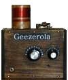 An Armstrong "Crystal" Radio Amazing performance from a radio that is easier and cheaper to build than almost any crystal radio. If you want to build a simple radio yourself, this is the one I suggest. from "The Old Geezer Electrician" Here is a much better looking version of the same radio  The Geezerola Senior regenerative radio
You might like to read the story of my Armstrong regenerative radio
that tunes shortwave and uses an FET for the detector,
 My Regenerative Shortwave Radio. I have written a little essay you might like that explains some of the principles behind
 How The Armstrong Superheterodyne Radio Works
If you have an antique AM radio and you need something decent to listen
to, perhaps you should buy or build your own
 Low Power AM transmitter |
|||||||||||||||||||||||