|
The Raytheon 7TP
The first truly practical transistor radio circa 1955 A comprehensive story containing historical, educational, technical and biographical elements & opinions by John Fuhring Introduction
Before you begin reading this story, I want you to know that what is
presented here is more than simply an article, but rather a long story
with certain autobiographical elements that I wrote for my own
entertainment. I am presenting this story to you free and
without commercials in the hope that you will be entertained by it.
Please feel free to scroll down and skip around if you don't wish
to read the entire story.
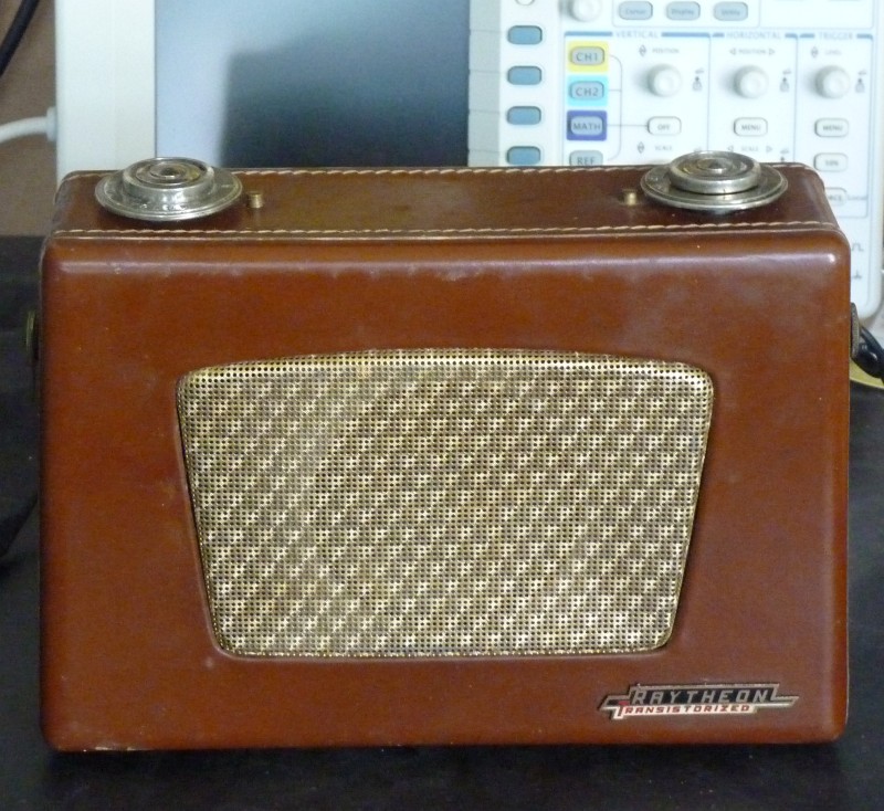 Dr. Z's 7TP transistor radio Circa 1955  The 7TP radio's chassis. Note the huge 'D' cells for power. Why they choose such large cells instead of smaller 'C' cells or the 'AA' cell is beyond me. Of course, with 'D' cells the radio will play all year long without having to change the battery. How I came to work on this radio
For many, many years now I have kept my horses at Lisa's place
located out in semi-remote, but still accessible region about 12 miles
from my house. The scenery out there is outstandingly beautiful with views of the
San Rafael and Sierra Madra Mountains, Gato Ridge and other topography
that makes this part of the world so beautiful and interesting. Lisa
has taken the most marvelous care of my horses over the years feeding
them only quality food and providing them with a roomy place to live. Lisa is also the daughter of one of my dad's doctor colleagues and a man who was a certified genius. Dr Z was interested and educated in all things that defines the "Renaissance Man." Dr. Z loved and was on top of all the latest technologies and dabbled in everything, especially things electronic. Back in 1955, when I was just a kid and most people (including Yours Truly) had never even heard of a transistor, Dr. Z bought this radio. The 7TP was maybe not the first transistor radio, but the first really practical transistor radio and many times better than the little Radio Shack radio that barely beat it to the market. On a personal note, looking back now, I am so, so sorry I didn't get to know Dr. Z when I was a youth because today I recognize that so many of our interests would have coincided and I sure could have learned a lot from the man. I really believe that if I would have only known him, the whole trajectory of my life would have taken a much better direction. Well, back in 1955 Dr. Z bought the 7TP radio that will be the subject of this story (actually a 7TP2 because it had a brown leather case). The radio stayed in Lisa's family after her dad passed away, but in an non-working condition. Unfortunately, the battery was left in and, of course, some of the cells leaked and caused some corrosion damage. So, that's how the radio sat for 40 - 50 years. Some months ago Lisa brought the radio to me and asked me if I'd restore it since even out at the stables I have a reputation for bringing back to life old dead radios with jolts of electricity there in my secret lab. Despite my reluctance to take on a transistor radio project, it was impossible to turn Lisa down because of all she has done for me and my horses over the years. Besides that, I was curious to see how the technology changed from tube portables to this very early transistor portable and in that, I wasn't disappointed as I shall mention later. A brief word on the manufacturer
This radio was manufactured by the Raytheon company in 1955. If you
recognize the Raytheon name at all you know it as a designer and
manufacturer of very high tech weapon systems for the U.S. military.
Some of us old geezers also recognize that they were the ones that
discovered the principle of the microwave oven from their extensive
work with World War Two RADAR. From almost the beginning, Raytheon was
into high tech stuff, but nearly all of their effort was directed
toward military uses of technology. Raytheon also had a brief interest in commercial uses of technology after WW2 and before the Cold War military spending spigots started to gush money. Although the first transistor was built in 1947 at Bell Labs, Raytheon's top engineers and scientists were very interested in early transistor technology, especially for miniature hearing aids and they wanted to get into the technology too. 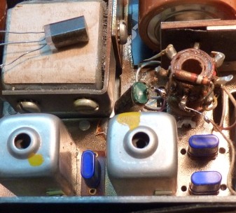 Raytheon's big black transistor operated at audio frequencies, but their special line of radio frequency transistors were painted a distinctive blue, came in a smaller metal can and were plugged into sockets Here we see V1, V2 and V3. 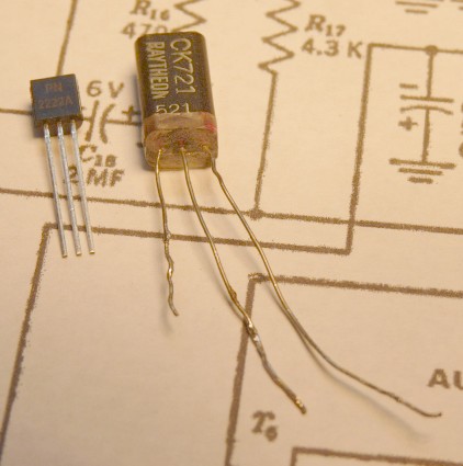 One of the very first practical types of transistors but made with a technology that would be obsolete within a year or so. To the left is a later silicon PNP transistor similar to the one I used. 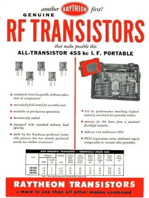 A 1955 advertisement for the first practical commercial transistors. Notice that the Ad includes a small picture of the 7TP radio. In these early days there were a lot of different transistor fabrication technologies out there and going deeply into any one technology was very risky. The companies with really dedicated solid state engineers and scientists picked a technology that made them money, but Raytheon picked a technology that eventually lead to a dead end and they went out of the transistor business by the early 1960s. The fact is, Sylvania, GE, Philco and others were way ahead of Raytheon. Since Raytheon's primary business had always been (and would be) weapons systems for the military, they closed their commercial manufacturing and today you only hear of them with regard to missile systems and such like. To me, the name "Raytheon" immediately congers up in my mind "Death Ray--theon" and something rather evil and sinister, but that's just me. Why I just hate working on transistor radios
You know, I hate working on transistor radios, especially those
that use early bipolar (PNP and NPN) transistors. Generally,
transistor radios are made super sub-compact with printed circuit
boards that are difficult to impossible to work on. Because of
their size and apparent complexity, it is very difficult for me to
follow the twists and turns of the circuit board while trying to trace
things using a schematic. For me, these inconveniences pail
compared to the other things I hate about transistor circuits.What I really, really hate about transistor circuits is how interdependent they are with regard to each other and with other circuit elements. What I mean is just this, if an element is somehow out of tolerance or isn't working correctly, it affects a whole string of other elements. Everything has to be in balance or the whole circuit is out of balance and so many times it's difficult to trace down exactly what is wrong. And then there is the fact that no two transistors are exactly the same and there are thousands of different transistor types. Oh sure, there are only two basic types of bipolar transistors, the PNP and the NPN, but within those two types, oh lord are there a lot of differences. This means that if you trace a problem down to a particular transistor -- say a CK721 -- it will be just about impossible to find the exact replacement. Lacking an exact replacement, a guy has to fall back on a "general purpose" transistor that in no way matches the original. Oh, and then there are the huge variations in parameters between transistors that making substituting transistors a very tricky business. Unlike tubes, transistor manufacture never was standardized. A 6BY7 tube could be exactly reproduced by any number of manufacturers and each one that came off the many, many assembly lines had characteristics that were virtually identical and certainly quite close enough that it didn't matter if you used a Dumont a Philco, a GE or an RCA tube. No so with transistors. When a run of transistors was made even by the same manufacturer, each one was different. Each was tested and if it behaved in a certain way, it was a 2Nx123 , but if acted another way it was a 2Nx456 or maybe it was a 2Nx789 and on and on and on. There was little standardization between brands because each manufacturer had their own line of transistor. I especially hate working of really early transistor radios because they used germanium as their semiconductor material and all of them were PNP types. After the early 1960s, silicon was found to be a superior transistor semiconductor and so geranium transistors manufacture was discontinued and now germanium transistors are impossible to find. silicon transistors don't directly substitute for germanium transistors because of the very different electrical properties of silicon and germanium. As mentioned, transistor circuits are finely balanced and putting in a element with different characteristics (like forward voltage drop, leakage, hfe, alpha, beta, different "Miller Effect" capacitance, Etc.) really upsets the applecart. I mean, it can be done and for this radio I have done it, but what a pain. Then there is the fragility of the transistor. I don't mean that a transistor is mechanically more fragile than a tube. Obviously a transistor is hundreds of times more robust when it comes to mechanical shocks and vibrations, but just put a little tiny too much voltage on it or short the biasing for just an instant and POOF, there goes your transistor. Probing a circuit can instantly destroy its transistor if the probe disturbs the circuit in any way. Replacing a bad transistor many times results in two bad transistors because whatever problem burned out the first one will burn out the second one before you finally discover what was really wrong. Tubes are infinitely more forgiving and almost nothing will cause them to be instantly destroyed, thus giving you plenty of time to correct something or remove the offending short or bad component. OK, here's a "real life" comparison between two radios with an audio output problem caused by the same malfunctioning component: The transistor radio is dead, but works before before the audio output stage. The tube radio sounds terrible, but does put out some sound. The first thing a guy would do is check the bias on the grid of the audio amplifier tube and doing so he would instantly discover that the bias is way too high, indicating a leaky input capacitor. Simply replace the capacitor and the radio will usually play and will not require the replacement of the tube. The output transistor will usually be found to be shorted out and being shorted, no bias measurements are possible so one is tempted to simply replace the transistor which will result in two burned out transistors. Finally, through extensive signal tracing and measurement of component values, the leaky coupling capacitor or the out of tolerance bias resistor is identified. A second transistor is successfully installed, but that's not the end by any means because now the circuit must be adjusted for the differences between the original transistor it was designed for and this new, quite different transistor you want to put in there. Finally, my mind tends to get a little confused when working with PNP transistors and, as mentioned, all the early transistors were PNP types. For years I was used to thinking of electrons traveling from the chassis or the return bus of a circuit to the positive electrode of an electronic device. When I was a kid and built many of the early projects from the Popular Electronics magazine, (using the infamous 2N107 transistor) I just couldn't wrap my mind around electrons moving from a very negative collector to the emitter and that all the voltages had negative charges. It just seemed unnatural that the chassis "ground" would be tied to the positive side of the battery. Finally, it was hard for me to get used to the fact that the minus bias on a PNP transistor is there not to limit current flow through the transistor as a minus bias does on the grid of a tube, but rather the bias is there to establish proper current flow in the transistor, wow was I confused. Of course, I later discovered that it really isn't that hard to "invert" your thinking, only you must spend some time with the schematic and you must never let the negative sign confuse you. By the way, when the 2N170 NPN transistor became available in my hometown electronics store back in the early 1960s (at $15 in today's money), I eagerly bought them to use in projects that seemed to be easier for my young mind to understand. However, I don't think I ever did understand transistor biasing all that well. If I hate working on transistor radios so much, this begs the question: how did I end up restoring a 1955 Raytheon 7TP transistor radio? Well, it's all Lisa's fault -- thank you Lisa for everything including this opportunity to learn something interesting. Starting the project
I am a little embarrassed to admit it, but the project
got off to a slow and bad start. I had other projects and other
issues going at the time, so I didn't even get the radio out of its
cabinet for some time, but when I did, I badly damaged an audio
coupling transformer (T5). I couldn't see a little screw that
extended down from the radio's case and scraped the transformer when I
tried to extract the chassis. I'll write more about this later.
After getting the chassis out, the first thing I did was to address the most obvious issue and that was all the corrosion caused by leaking battery cells. After I got the chassis out of the case I could see and assess the corrosion damage the battery had done and it was extensive. I cleaned up the rust and corrosion and epoxied in certain riveted parts that had corroded through and got it, if not looking new, at least in usable condition. 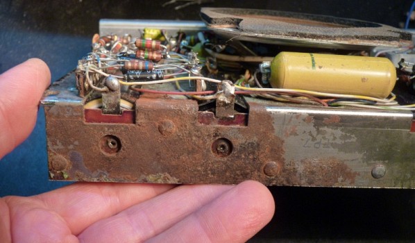 This isn't the only corrosion damage As I mentioned, I damaged one of the audio transformers while taking the chassis out of the case and all because of that damned hidden screw and my impatience. 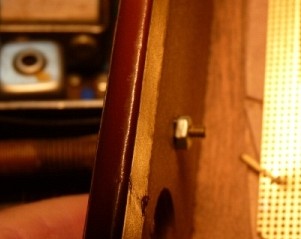 Danged little screw. Why they installed it hidden this way and right above a fragile transformer is beyond me. 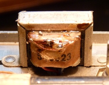 I had to repair this transformer because getting a replacement would have been impossible
After I repaired the transformer and after I
replaced all the many electrolytic capacitors, but before I replaced
the paper/wax capacitors, I attempted to get some sound out of the
radio, but heard nothing. For some reason this discouraged me and
I got it into my head that this radio would take a lot of
troubleshooting, so I'm sorry to admit it, but I put the radio in the
back corner of my workbench and let several months go by before doing
anything further on it. However, I did make an inventory of all
the capacitors that would need replacing and I did make up a kit.
Not having a schematic caused a big delay
There is one thing I didn't have and that was a
proper schematic. I couldn't locate one and I didn't want to
trace all the circuitry and try to make up my own schematic, so I just
let the radio set until I could figure out how to get a schematic.
My number one rule is to never start a project unless you have a
good schematic, but here I violated my own rule and it came back to
bite me.All my usual sources of schematics failed me so until just a month ago this is how matters stood. The radio was only half restored and I no schematic and that's the way it sat "on the back burner" for months and months. A couple of weeks ago Lisa asked me about the radio and that brought it to my attention once again and since I had no other projects pending, I finally got busy and started looking for a schematic. The little paper tag glued to the case indicated that the radio was a Raytheon 8TP2 and so that's what I started looking for. I joined the Radio Museum as a dues paying member and looked up the 8TP2 radio. There was a picture that looked exactly like my radio, so I downloaded the schematic of the 8TP and went to work. 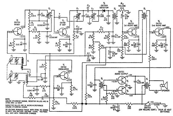 The original factory design of the 7TP radio circa 1955 Getting the radio to work -- sort of
I thought I'd trace the signal path from the
antenna through to the second detector stage with my oscilloscope to
see where I was loosing signal. I couldn't make sense out of
what I was seeing in the chassis using the schematic I downloaded.
Nothing made sense at all and then I thought of something, since
this radio had only 7 transistors, maybe this wasn't an EIGHT TP
(assuming TP stood for 'transistor portable') but was instead a SEVEN
TP. Well, I looked up the museum's 7TP and by golly, there it
was. Now all the circuits made sense and I had something I could
really work with.Before I could trace the signals through the radio, I had to be sure all the old paper/wax and electrolytic capacitors were replaced or I'd just be wasting my time trying to trace signals. 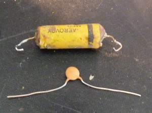 Old technology 300 volt paper/wax capacitor and a modern 50 volt ceramic cap below it. After all these many months I finally replaced all the old capacitors (except one) from my kit of parts I bought a year or more earlier. When I had them all in, I applied power to the radio making sure that the chassis was the positive side of 6 volts. Again I heard nothing and on tracing the signals, I discovered that the audio output (push pull) stage wasn't working. I got no signal out of the output transformer (T7), but I did notice that one of the old CK721 output transistors was very hot to the touch indicating it was shorted. My heart kind of sank when I realized that this transistor was destroyed (probably through moisture getting in there over the decades) and causing it to go into "thermal runaway." I did a quick search to see if the CK721 transistor was still available, but at around $50 apiece, I didn't think it was worth it especially if there was something else wrong that would destroy it too. 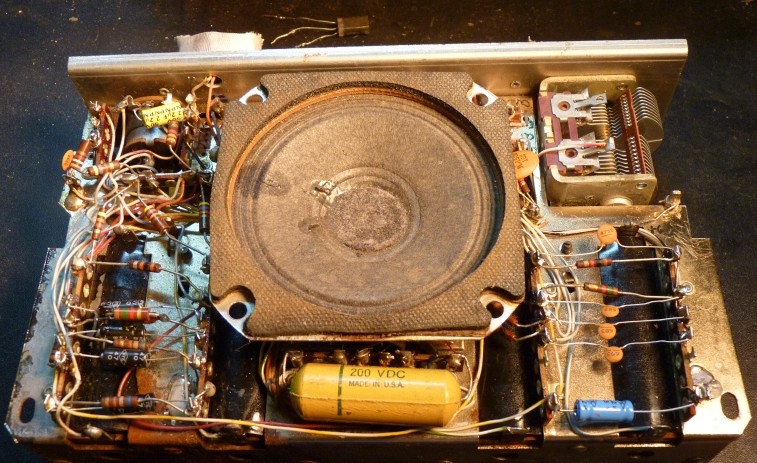 The chassis from the rear, battery side down.
Most of the electrolytic capacitors are on the left soldered to their terminal strips while many of the modern ceramic capacitors can be seen on the right. The new technology capacitors are many times smaller than the original capacitors and so there is a lot of free and empty space. Note the hand wired point to point wiring with the components hand soldered into terminal strips just exactly as tube radios had been made earlier. Substituting "modern" silicon transistors
The original CK 721 transistors in the output stage
were gone so I figured that I had nothing to loose by removing them and
trying
two PNP silicon transistors that had the power dissipation that I'd
need. Well, the first attempt was a disaster as they went into
thermal runaway and were destroyed. I changed the bias resistor
to match the greater greater junction barrier voltage of a silicon
transistor and discovered that the 100 ohm resistor was bad. The
bias resistor's function is to bias the transistors so that there is no
or almost no current flowing through the transistors when there is no
audio signal present. This establishes a "crossover" point where
one transistor conducts when the audio signal just starts going
"positive" and the other conducts when the audio signal just starts
going "negative" and if the crossover point isn't carefully adjusted,
you get the dreaded "crossover distortion" which I'll discuss at length
later. I thought I had the problem licked, but the radio still sounded bad and then I noticed that there was a resistor in there that fed back some of the output of the speaker's transformer to the input of the driver stage. I had never seen anything like this done before and I could only make guesses why it was in there. Obviously it was causing distortion and an oscillation that caused so much current to flow in one of the silicon transistors that it burned it out --- again. I was very reluctant to mess with the biasing of the ancient V5 (CK721) transistor for fear of hurting it, but that resistor just had to go. By taking measurements of the biasing of the V5 transistor, I discovered that removing the resistor would have no effect on biasing, however I was still a long way from having a restored and operating radio. These new high gain NPN silicon transistors I put in there had a huge amount of crossover distortion and the radio, although now making sound, sounded just horrible. I just couldn't get the right balance of bias voltage on the transistors. Just when I thought I had the bias right, one or the other transistor would start running away and I destroyed an additional transistor. I tried using an ordinary silicon diode to establish the bias because it would have the same junction barrier voltage as the transistors, sort of. In other words, simply by replacing the bias resistor with a silicon diode, the push-pull stage should be biased close to Class AB2 operation and the transistors could not go into thermal runaway. By golly, it seemed to work, but only later did I realize that at low volume, the crossover distortion was bad and this diode bias was no solution after all. I'll discuss the troubleshooting I did and how I finally got the radio working properly, but first I want to change the subject and say something about how this radio works. How this radio works
for hardcore nerds only
It seems to me that this radio was designed by people
who were more used to designing for tubes because the design principles are so similar.
Even the identification of the transistors (V1 through V7) uses
the 'V' for valve designition that was (and is) common with tube radios, but the 'V' was
soon to be dropped in favor of identifying transistors by 'Q' numbers.
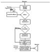
The 7TP is a conventional Armstrong superheterodyne consisting of a tunable local oscillator, a mixer to produce the intermediate frequency (IF), IF transformers for bandpass filtering, an IF amplifier, a diode detector for recovering AM audio and three stages of audio amplification to boost the audio signal up to speaker level. Transistor V1 is a mixer who's base is connected to a coil that picks up the radio station from the ferrite loop antenna. This pickup coil also has on it the oscillator signal from the V2, the so-called local oscillator (LO). The station frequency and the oscillator signal mix in V1 to produce a 455 KHz IF signal which is filtered by T3 and then amplified by the IF transistor, V3. The amplified IF signal is further filtered by L1 and L2 and then the audio is demodulated by V4, a germanium diode detector. Again, the diode is designated with a 'V' number as if it were a valve (tube), but soon diodes would be have a 'D' name. The audio thus detected goes to audio transformer T4 where it is coupled to the volume control potentiometer. There is a network on the V4 side of the T4 transformer that forms an automatic volume control circuit (AVC). A strong carrier produces a negative DC voltage and through a network of resistors and capacitors, that AVC voltage, going up through coils in T1 and T2 changes the bias on the mixer, V1 to make weak stations louder and cut back on strong stations. See what I mean about everything being so interactive and thus hard to tell what might be wrong with a circuit? After detection and recovery of the sound, the low level sound is amplified by transistor V5 where it is coupled over to transistor V6 through audio transformer T5. From V6's collector, the signal is connected to transformer T6. The output of T6 (the secondary) is phased split and feeds the bases of the push-pull audio output transistors V7 and V8. A push-pull (class AB2) circuit is used in radios like this because there is no power wasted and the power output transistors run a whole lot cooler than a single transistor running at class A. By the way, for proper sound reproduction, the amplifiers must run at class A or if the transistor is biased for the more efficient class B, there must be two of them working in push-pull so that the result is a class A amplifier. Here's how this radio's class AB2 amplifier works: When the audio waveform at the primary of T6 is going -- say -- "positive", one leg of the secondary of T6 is going positive too and other side is going negative (opposite phases input circuit). The side going "positive" biases the transistor it is attached to even further into cut off and no current flows through this transistor. When that transistor is cut off -- let's call it V7 -- it no longer conducts current through its collector to the output transformer T7. On the other hand, the "negative" going wave that is produced at this exact moment at the secondary of T5 biases V8 into an "on" state and a proportional (linear) current flows through its side of T7's primary windings resulting in a speaker voltage at the secondary of T7. When the waveform reverses, it is now V7 that conducts and V8 is cut off. It is that critical region where the waveform goes through zero going from positive to negative (or vice versa) that is is what's known as the crossover and the biasing on the base of the transistors must be adjusted for a smooth crossover to prevent "crossover distortion" and bad sounding audio. In other words, when the waveform is at zero, both transistors must be biased off, but just barely biased off so that when a tiny voltage starts building up in the audio waveform, one or the other transistors starts to conduct in a linear fashion. 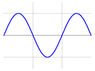 Audio wave at the primary of
transformer T6 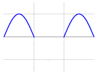 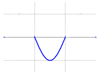
Turn on bias at the base of V7
Cut off bias at the base of V7
 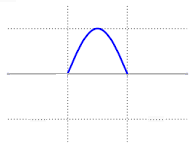
Cut off bias at the base of V8
Turn on bias at the base of V8
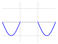
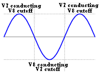 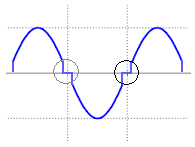 Resulting waveform at the Too little static bias causing speaker (after combination crossover distortion in transformer T7) The AB2 amplifier is perfect for battery operation because they draw a lot less current than a single transistor class A1 circuit of equivalent power output and the AB2 amplifier is as linear and sounds just as good. The reason for this is because the A1 amplifier's transistor is biased so that it operates at a 100% duty cycle whether the radio is playing loudly of softly. The duty cycle of an AB2 transistor is never more than 50% and only reaches that at the highest volume levels. Normally the duty cycle of an AB2 is waaaay below 50% and it only draws current from the battery as it needs it. Finally I should mention that the push-pull (double phase) currents from the collectors of V7 and V8 are at relatively high impedance (~6 volts and ~0.2 amps) and can't drive a loudspeaker directly. T7 combines the two (double phase) collector currents from V7 and V8 and transforms their relatively high impedance down to 8 ohms which drives the (single phase) loud speaker (~3 volts and ~0.4 amps). Troubleshooting the audio problem
The two original CK721 transistors in the push-pull
circuit were biased for a class AB2 amplifier crossover configuration
by resistors R26 and R27. Of course, when I put in the two
silicon PNP transistors in place of V7 and V8, the crossover bias was
all wrong and way too low (silicon junction voltage is double that of
germanium). After experimenting with biasing resistors and burning up a couple of transistors, I tried using a silicon diode to establish a safe crossover bias because, being made of silicon, the diode would have an junction drop of 0.6 volts that would be close to the static crossover bias necessary for those new transistors. In other words, if you put 0.6 volts on the base of a silicon transistor (-0.6 for a PNP), the transistor is cut off (but just a little too much) and is close to a class B amplifier configuration. Add another transistor identically biased but fed 180 degrees out of phase and you have a class AB2 amplifier --- sort of. To my mind at the time, the amplifier stage biased this way should have worked and for a while that's the way I left it. The more I tinkered with the radio, the more I realized that I just wasn't satisfied. After extensive listening and tuning around, I realized that the radio sounded pretty good if the volume was turned way up, but pretty bad when it was turned down to normal listening level. This just wasn't satisfactory and so I tried something exotic. The Adafruit experiment
I had earlier bought one of those tiny, tiny amplifier boards from
Adafruit that has a class 'D' amplifier chip on it (PAM8302 amplifier).
When I first got the board ($ 4 for the board and $ 4 for the
shipping), I was absolutely amazed at the level of sound you could get
out of the tiny little thing. Another thing that amazed me was
how cool everything on the board stayed, even at full power output.
In addition, the marvelous little unit has a differential,
reasonably high impedance audio input and a screwdriver adjustable gain
level. I was sure that the board would be perfect for this
application so I wired it up and hot-glued it in as shown in the photo
below. I proceeded to congratulate myself for finding a quick and
easy solution to this vexing audio problem even if I was modifying the
radio in a very radical sort of way. Ah, but there were problems
and eventually I had to go back to the drawing board.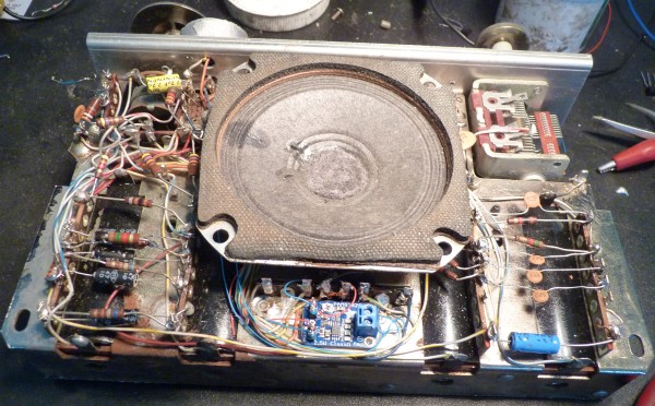 Adafruit class 'D' amplifier neatly installed in the lower center of the chassis. 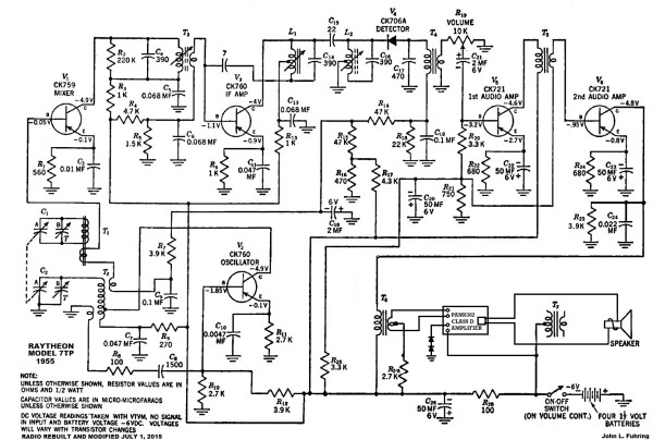 The Adafruit board wired in (lower right) with transformer T7 bypassed. I thought this was the answer until I discovered a horrible amount of RF interference. These boards would never, never pass FCC Part 15. Even before putting in the Adafruit board, I had noticed that the two original geranium audio transistors (V5 and V6) were extremely noisy and even if they had a clean signals going into their bases, the signal coming out the collectors had a huge amount of "white noise" on them. This was especially true of V6, the output driver transistor, it was extremely noisy. I don't know if the noise was because of the very, very early fabrication techniques of these transistors or if the geranium crystal got contaminated by moisture over the decades. Something had to be done about the noise, so I looked at the schematic and I realized that the original designers had made a bad mistake. They had put the volume control potentiometer in the wrong place and that it really should have been connected to the input to the driver transistor (V6), not to the input to the audio preamplifier (V5). The solution was to "move" the potentiometer over to the driver transistor. Actually it was pretty easy to rewire the potentiometer by simply moving a few wires and capacitors and so I did. Changing the function of the volume control really helped a lot, but the radio still put out a lot of noise with no signal present and a lot of noise would accompany weak or quiet signals. This accompanying noise made for a very poorly performing radio. I finally decided that transistor V6 was just too noisy and it would have to go. With great reluctance I replaced the noisy CK721 with a low gain, low noise Motorola BC416 silicon PNP transistor. Wow, what a difference. The static noise level with the volume turned down went from annoying to nothing and at first it was so quiet, I thought I had done something wrong. With this solution to the noise problem and the Adafruit board installed, I thought I had the radio ready to give back to Lisa, but I had to give it a more complete trial before certifying it as ready to go. During my tuning around on the AM band, I discovered some fatal (and I mean fatal) flaws in the Adafruit amplifier board that doomed its use. There is something rotten in Denmark and with my Adafruit board
To my great surprise, I discovered that the class
'D' amplifier on the Adafruit board puts out a huge amount of RF
interference at several locations on the broadcast band. This
interference is strong, it sounds terrible and makes using this little
module impossible. This little board is in clear violation of FCC
Part 15 and perhaps this is why I never heard of using a class 'D'
amplifier before. No, the Adafruit board, cute as it is, would
have to go. Fortunately, a little hot air from my heatgun
carefully applied to the board softened the hot-glue and I was able to
remove the Adafruit
board and pull out all its wiring without damaging anything. So,
there I was, back at square
one trying to get a couple of modern silicon PNP transistors to work
in the original Class AB2 amplifier. Finally getting the radio to operate well
After removing the class D amplifier board I again
played with the bias on two push-pull transistors and again I
burned up two more transistors, but just as all hope was lost, I had
this "brilliant" (for me) insight. Dense as I am, I finally
remembered and realized that I wasn't working with tubes and bias
voltages, I needed to think 'transistor' and bias currents.
Instead of trying to use a voltage divider and set a voltage for these high gain transistors, I
should use a large value resistor in the base circuit and let the transistors draw
a small current. Since these transistors are (as mentioned) high gain, all
I would need is a tiny current from a single high resistance at the center of T6's secondary and that
would insure that my transistors wouldn't overheat and burn out. Wow, wow, wow, did that work well. I put in a single 75 K ohm resistor from the negative side of the battery to the center of the input transformer's secondary and that caused these high gain transistors each to draw a small current that established a good crossover point for class AB2 operation. Oh joy, the radio was now low noise, the audio was very sensitive and easy to listen to with no distortion and because of this, I could hear weak stations that I couldn't hear before. Best of all, there was NO RF interference and no overheated transistors. Boy, if I would have only thought of this in the beginning, I would have saved myself hours of frustration. 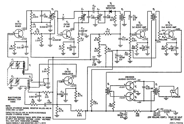
The present schematic of the 7TP showing the modifications
necessary to replace the CK721 output transistors, the noisy driver transistor and the relocated volume control. Conclusions
Finally, the radio is restored and is working just
great. Except for a few minor changes, the radio is in a
configuration very close to its original design.
No, it is not completely original with original parts and yes, I had redesigned
the audio section slightly, but now the radio performs as well and
sounds as good as it did when it was new back in 1955 and as well or better than a modern AM portable radio.The radio as an interesting and important "missing link"
In paleontology we have several examples of
so-called "missing links" although paleontologists just hate that
expression and prefer "transition fossils." Throughout the
geologic record there are numerous fossils that show transition
features that point to the evolutionary paths that all animal and plant
life on earth has taken. For example, there are very old, very
primitive amphibian fossils that clearly show features of the fish they
evolved from. Seymouriamorphs were amphibians that were on their
way to becoming the first reptiles. Likewise, there are
certain reptiles from the Permian that show mammalian features back
when there were no mammals and then later, early creatures that were
clearly mammals, but showing reptilian features. These so-called
"missing links" don't "prove" that we, as mammals had ancestors that
were fish, and later ancestors that were amphibians and still later
ancestors that were reptiles, but the evidence is there and it is very
strong and it doesn't rely on magic or myths to explain why we are
related to all life on earth.The evolution of electronics from spark gaps to personal computers is also full of transitional fossils too. One such transitional device that shows characteristics of its earlier tube ancestors and yet is a fully functional transistor radio is the 7TP. All the original capacitors were directly from tube technology with working voltages in the hundreds of volts. Of course, when I replaced those capacitors I used much smaller capacitors with only 50 working volts, a voltage more suited to transistor equipment. Even the way the transistors were laid out reminded me of triode tubes and what had to be done to "neutralize" them so they wouldn't self oscillate. What really indicated to me that this was a radio designed by guys who were used to designing tube radios is how all the components were soldered to terminal strips and interconnected with wires and all installed by hand. A Final word
Is it important to know the history and operation of this
radio? In a word, no. For the vast majority of people who
simply consume electronic products for the marvelous kinds of
entertainments that are now available, the invention and evolution of early
electronic technology is beyond their understanding and beyond their
least desire to know. It is only for the tiny few of us who like
to delve into this early technology simply for the fun of it and
certainly not for any kind of career or profit. In the end, it's all a
question of what makes you happy and what interests you and, in some
cases, what satisfies your unique expression of that human trait called
curiosity that we all have to a more or less degree and that can take
so many different forms.
The next question is, now that this wonderful old 7TP radio is working once again, is it good for anything? Yes, it can receive AM broadcasts as well as any portable AM radio (and better), but is it worth tuning in on AM radio? For me personally, no. The only AM radio I listen to on a regular basis is a rebroadcast of my favorite FM stations that I do through my own little AM transmitter. THE END
Having arrived this far,
obviously you have a superior attention span and reading ability that
far exceeds that of the
majority of web users. I highly value the opinion of people such as yourself, so I ask you to briefly tell me:
If you have an antique AM radio and you need something decent to listen
to, perhaps you should buy or build your own
 Low Power AM transmitter I
have a lot of other old radio and early technology stories on my website
 For
other stories and things,
|