AN ARMSTRONG "CRYSTAL" RADIO using the silicon crystal inside the FET as the crystal A project from the book "The Old Geezer Electrician" by John Fuhring
Foreword to the yet to be published book The Old Geezer Electrician
Back in the
late 50s and early 60s my nascent career in electronics was encouraged
by the many wonderful construction articles in Popular Electronics,
Popular mechanics and Popular Science magazines, but it was a 1940
edition of an old book I found in the City Library that really got me
going. That old book
was written by Alfred Morgan and was titled "The Boy Electrician."
Mr. Morgan and his "Boy Electrician" book went back a long
way, with the first
edition printed in 1913. By the time I got this
book,
around 1958, the technology in it was already 20 to 50 years old.
Still, the book contained a lot of good, solid basic stuff
and
several wonderful projects that a kid could build and learn while
doing.
One project that really caught my fancy was the Armstrong Regenerative radio. I had built and experimented with crystal radios before, but I was ready to move up to something better. I was very lucky because the 1H4 tube the project required was still available, otherwise the project might have ended right there. Of course, I did not have the skill and tools to build the radio as it was described. The specified tube socket and the exact coil form were both unavailable, but half the fun of building this radio came from the opportunity to improvise (like using a toilet roll for a coil form) and to invent construction techniques that matched my building skills. 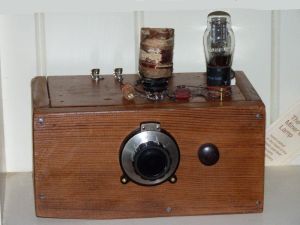 My regenerative radio from 1958 There is a link to my regenerative radio here and at the end of this story. This radio is functionally identical to Armstrong's 1911 radio except that my 1H4GT triode is a much better tube than his Audion triode was. Both this and Armstrong's radio need an 'A' battery and a 'B' battery. 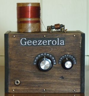 The (in)famous 2012 Geezerola Radio. (Geezerola is just a silly name I chose, you can call your radio anything you want) This little radio is functionally identical to Armstrong's 1911 and my 1958 triode tube radios except, unlike triode vacuum tubes, the crystal in my triode will pass electrons without heating the cathode. Without the need to heat a cathode, my radio needs only a single (9 volt) battery.
Well, a lot of
time has passed since I built the Boy Electrician radio (yeah, like 55
years), but I can truthfully say that the
little project did exactly what Mr. Morgan intended it to do.
It
took a
young boy, me, and it inspired him to go on and learn more about
electricity and eventually make his living working with electricity.
I was that "Boy Electrician" and now I am this "Old Geezer
Electrician." In my status as "Electrician Emeritus" I plan
(in a
very small way) to emulate Alfred Morgan and present a little
regenerative AM radio for the education and inspiration of all the
aspiring Boy Electricians, Girl Electricians, Adult
Electricians and even my fellow Old Geezer Electricians. What
is
more, I am presenting this as a building project using the same simple
skills and techniques that just about everybody possesses and that I
used to build my 1958 radio.
So, here's the first chapter of my proposed book "The Old Geezer Electrician" and I hope you like it. Introduction
A while back I got working one of the best crystal
radios that was ever offered to the buying public, a Heathkit CR1
receiver. As I experimented with it, I was very impressed
with its performance both in terms
of its excellent selectivity and, for a crystal radio, its sensitivity.
On those evenings when the "skip" is in, I can hear
stations over 200 miles away.
After having fun with my CR1 and impressing myself with its performance, I thought I'd do a performance comparison between it and my 1958 "Boy Electrician" regenerative radio. Even as far back as 1958 I knew that my Armstrong tube radio was far superior to any of my simple crystal radios, but now I had this excellent CR1 crystal radio at my disposal so that I could now compare a good crystal radio to a simple regenerative radio. As good as the Heathkit CR1 radio is, it was completely and totally outclassed by my old Armstrong radio. Once again I was impressed by the old regenerative radio's selectivity -- about as selective as a superheterodyne -- and I was impressed with how well I could pull out the weak, far away stations and hear them clearly even with a short antenna. There was no comparison really. The CR1 crystal radio is fine for listening to strong local stations if they aren't too close to each other and if you have a huge long antenna, but it is greatly inferior to my old regenerative radio in every respect. The difference in performance between a good crystal radio and even a simple regenerative radio is so profound, it set me to wondering why anybody today would bother building a crystal radio especially when you consider that such a radio is just as cheap and easy to build as the simplest crystal radios. So, if a simple FET regenerative radio is so superior to any crystal radio, what can account for the fact that crystal radios never went totally extinct and people are still building them? Well, there is a great appeal in building and using a radio that is so primitive and so simple that it needs no "high tech" components or even a battery. I mean, a crystal radio can be made from materials that have been available to people since before the Bronze Age. All you need is copper wire (available since 5,000 BC) and a rock crystal (available since 4.5 billion BC). Add that to the fact that the energy to produce sound in the headphone is "free" and comes from the radio station, building and operating crystal radios are still fun. A big waste of time (in my opinion), but still fun. Simple homemade radios go high
tech
The better and most useful crystal
radios that
people build today are not much like the crystal radios of the past.
Today's crystal radios are pretty "high tech" and are built
with
modern
components that our ancestors didn't have. The thought has
occurred to me, if today's crystal radios are so high tech, why not go
a little further and replace the crystal diode detector with a Field
Effect Transistor (an FET) which contains a tiny
piece of silicon crystal? Both the crystal diode and the FET
rely on a crystal of geranium or silicon to work, so why not call the
FET radio an Armstrong
"Crystal" Radio? Yes, I know, the
crystal
radio purists will be shocked to hear somebody call an
amplified radio with a battery a crystal
radio, but I'm going to call my little radio one anyway.
Is my Armstrong "Crystal" radio really so much better than anybody else's crystal radio? Frankly, my little radio is as cheap, easy and simple to construct as the most basic crystal radio, while at the same time it is vastly more sensitive and is vastly more selective than even the most elaborate high performance crystal radio. These are not just words, I invite anybody to compare the performance of their best and most complex crystal radio with my simple Armstrong "crystal" radio. Simply by substituting a common and inexpensive Field Effect Transistor (an MPF102) for the 1N34A diode, adding a tiny battery and changing a few circuit elements around, I have built a little radio that will run rings around anybody's crystal radio. So, let's compare my crystal radio's parts list with my Armstrong crystal radio's parts list.
As you can see, both radios use similar parts and the difference in cost between the two radios only amounts to a couple of dollars either way. My little radio is as simple as the most basic (very poor performing) crystal radios and it is as cheap to build, but (and this is an important 'but') it vastly outperforms even the most elaborate crystal radios. Because of all this, I think that the choice is obvious, the Old Geezer Electrician radio is what you should build. Building the radio
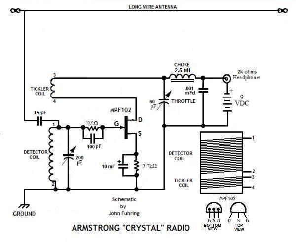 Armstrong "crystal" radio schematic diagram. How the book "The Boy Electrician" would have shown this schematic. Of course, there were no FETs back in those days.
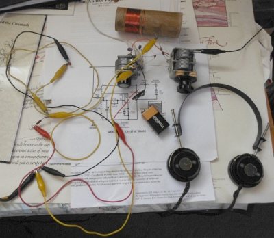
Before
finalizing the schematic and writing up a story for my website, I
needed to prototype the radio, get it working and see if it would
really work and be worth building
By the way, the current draw from the 9 volt battery is a whopping 0.9 milliamps. Yes, the radio draws all of 0.0009 amps and at 9 volts, it burns 0.008 watts (8 milliwatts) of power. I wonder how many months a 9 volt battery would last at that rate if I left the radio on day and night? Fortunately for the battery, when I remove the headphones from the jack, it cuts the power and no current flows from the battery. Isn't that a cool way to avoid having an on/off switch? Due to the miracle of the human ear and the extreme efficiency of my magnetic earphones, this tiny wattage is so loud I have to shove the earphones forward off of my ears when listening to a local station. The "MYSTERY OF THE GATE TICKLER"
circuit.
Lately (July 2014) a gentleman asked my
why I
bothered to
include the "gate tickler" circuit since an FET's gate does not collect
electrons and they don't self biases as triode tubes do.
Of
course they don't, that's why I included the 2.7 (or so)K resistor and
10 uF capacitor in the source circuit, but in this case, the gate
tickler circuit is not for biasing, but to improve the performance.
At first, I too assumed that the gate tickler was not necessary and I built my prototype without one. My prototype failed to perform as well as my 1958 tube type regen and so I searched for ways to improve it. When I added the gate tickler to the prototype (on a sort of a whim), I experienced a very noticeable improvement in the overall performance of the radio, including improved sensitivity, easier tuning and easier throttle control. With the gate tickler circuit in there, the performance of the FET radio is fully equivalent to the performance of the triode tube radio. Please don't ask me why because I'm sure the answer is way beyond my level of theoretical knowledge, but gee does it work and you can't argue with success. Getting down to brass tacks
You know, I've always wanted to build
another
simple, low cost, high performance radio using brass nails driven in a
wooden
board for mounting the parts, but the new radio would feature a simple
and cheap Field Effect Transistor (
FET) instead of the big, rare and fragile triode tube and its big
battery set. I got the idea for mounting parts on a wooden
board
with screws and nails 55 years ago when I
built my Boy
Electrician radio and I always thought I'd like to do it again.
In fact, when I was an idealistic young man, I thought this
ultra
simple and ultra cheap way of building a radio might be an ideal
project for really poverty stricken places in India and Africa so that
kids there could learn about electronics and even very poor people
could listen to the radio. Well, I soon realized that in
those
kinds of places, simply buying those very inexpensive factory made
transistor radios was the best way for them to go and the kids had no
access to transistors, resistors, capacitors or soldering irons.
Regardless of all that and after all these years, I've finally done it, I built a simple transistor regenerative radio based on this ultra easy and ultra cheap construction technique and you know, it is still a fun, quick, cheap and easy way to build something that really works and works surprisingly well. As I did with my first regenerative radio, I used a paper toilet roll as my coil form and I simply glued it to the wooden chassis board. Shortly I will describe doping the paper tube and how to wind the tuning and tickler coils on the toilet roll. Besides an ultra-cheap radio with outstanding performance, my main goal was to design something simple enough so that anybody could build it with just ordinary tools, simple skills and just ordinary craftsmanship. To accomplish this, I went back to the late 1950's and repeated the original building techniques I used to build my "Boy Electrician" radio. Of course, there is no reason why you can't build it to look nicer if you want to, especially if you have the tools and the skills -- and the patience for that sort of thing. Just remember this, "Hansom is as hansom does" and as crude as it looks, this little radio performs quite handsomely and will perform every bit as well as the better looking projects. If you are looking to build a nicer version of this radio, I recommend building the Geezerola Senior. There is a link to that project at the end of this story. The Geezerola Senior is only slightly more difficult to build, but it sure looks nice. If you decide to build this
radio, here is what you will need:
1) A wooden "breadboard" also known as the circuit board.2) A thin wooden or sheet metal panel or enough thin boards to make a box. 3) A large knob for the main tuning. 4) A smaller knob for the throttle 5) A paper toilet roll 6) 10 feet of 30 Ga. magnet wire 7) A few inches of 18 Ga. insulated wire 8) An MPF-102 (or similar) FET transistor 9) Two plastic variable capacitors (60 pF & 140 pF dual units) with shaft extensions from Scott's Crystal Radios. 10) A 1 megohm resistor 11) A 2.5 mH choke coil. Tiny, low current chokes work great. Check e-bay. 12) A 2.7 K ohm resistor, 1/8 watt or larger. 13) A 0.001mF capacitor (50 volts or greater) 14) A 100 pF capacitor (50 volts or greater) 15) A 15 pF capacitor (1KV) 16) A 3.5 mm phone jack to fit your headphone or earphone plug 17) A 9 volt battery 18) A battery holder 19) Brass plated nails or small brass wood screws and two small screws for the Farnstock clips 20) Wood glue. Elmers white Gorilla Glue works great. 21) Two Farnstock clips. 22) My old Navy 600 ohm headphones work very well and so do my traditional 2,000 ohm headphones. Philmore sells a rugged and inexpensive 2,000 ohm earphone that works well too. "Crystal" type piezoelectric headphones or earpieces work well but you must place a 2,000 ohm resistor across them or they won't pass enough current. If you use low impedance headphones, you will need a 2,000 to 8 ohm audio transformer. Small transistor type transformers work fine. If you configure your radio with a transformer or a resistor in line with the battery, you will need to add an on/off switch or the radio will be on even if you aren't listening. Tools you will need:
1) Drill and bits2) Round file for enlarging holes 3) Screwdrivers to fit the screws you will be using 4) Ruler 5) Small hammer 6) Small saw 7) A low wattage soldering iron with a sharp tip. 8) Electronics grade (rosin core) solder. Having a jar of extra flux is really nice. 9) Needle nose pliers. I really love using hemostats for doing fine work. 10) A "Dremel" type grinding tool if your panel is thick and you need to counter-sink the phone jack. Suggest layout and
building instructions.
You will need some kind of front panel for
mounting the
tuning
capacitor and the throttle capacitor. Perhaps the simplest
construction would be to make up an 'L' shaped bracket with the
components on the bottom board and the capacitors mounted above them.
In that case, I suggest that you drive the brass plated nails
in
from the underside so that nothing protrudes through to the underside.
However, the way I made my radio was how I made the original
tube
model
back in 1958. I began by cutting up five 1/4 In. thick
basswood
(linden wood) pieces to make the crude wooden box that you can see in
the pictures. I mounted the
coil and most of the parts on the top deck and the tuning capacitors
inside the box and on
the front panel. The inside is also where the
battery
holder is mounted. As you can guess, the exact measurements
of
the wooden pieces are not important. You can figure out for
yourself how large to make it based on the wood you use.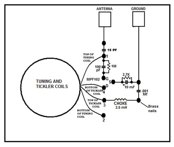 Top deck layout of my radio. I mounted a phone jack, the tuning capacitor and throttle capacitor on the front panel below this deck. The battery is mounted in a holder on the inside of the bottom deck. The large black dots are brass plated nails. Detailed building instructions
Begin the project with the coil form. Just as I had
done
55 years ago when I built my "Boy Electrician" radio, I used a toilet
roll for the coil form. Toilet rolls are still made of the
same
flimsy paper that must be soaked in a dope of some kind to make them
stiff and so they won't fall apart. It seems that toilet
rolls
are larger in diameter (1.70 inch) than they were when I built my
earlier radio
because my modern roll will easily slip over my 1958 coil (1.55 inch).
The
next paragraph tells you the length of my main and tickler windings,
but you should
know that for small diameter paper rolls, you will have to use slightly
more wire and thus more turns to get the same inductance.
Once
you have the nails driven in, the antenna and ground connectors, the
tuning capacitors, the phone jack and the coil all mounted, you can
begin to mount the small components and wire everything up as follows:To make the tuning coil, I began by drilling two tiny holes next to each other, and then two tiny holes 0.9 inches down the tube from them. I threaded the No. 30 wire through the first two holes so it was secure and wouldn't pull out then began to wind the tuning coil. It is always a good idea to make the tuning coil too long at first so that you will later have to to take some turns off. When I was done winding I had a coil that was 0.820 inches long. No, I didn't bother to count windings, but there was something like 85 altogether. If you use a smaller diameter paper roll, I suggest you wind 90 or more turns. Don't worry about making it a little too long because you will take some turns off later when you make your final adjustments. To make the tickler coil, I drilled similar small holes side by side, threaded No. 30 wire through them and wrapped about a 10 turns on the roll, made two more small holes and threaded the end through them. Try to keep both the coils tight and regular with all the turns close together. There should be about 1/4 inch or so between the tickler and tuning coils, but the distance isn't too critical. After you have the coils wound, it might be a good idea to paint some varnish or dope over them because you will be adjusting the number of turns later and you don't want the coil to come apart. I'll be saying more about this "cut and try" method of adjusting coils very shortly. When your coils are complete, go ahead and smear on some glue around the bottom edge and glue it to the wooden circuit board as shown in the pictures. Just let the coil wires dangle for now. Partly drive in the nails from the top of the circuit board if mounting everything on top or drive in the nails from the bottom all the way in if mounting everything inside the box. Use the photo and diagram as a guide to where and how to place the nails. With tiny drops of glue at the edges of the variable capacitors, glue them to their panel with the shafts sticking out. The capacitors used in this project have two sections, a 140 pF and a 60 pF section. For the tuning capacitor, the two sections will be bused together with a piece of bare wire for a total of a 0 - 200 pF. For the throttle capacitor, you will use only the 60 pF section. With the Dremmel tool and a grind stone, countersink a hole in the panel and make the wood thin enough to enable the phone jack to go through the panel and be screwed down with its nut. You may locate the phone jack anywhere you wish, but I found the lower left corner of the front panel an ideal place. You will need some way to connect to the antenna and ground. It is up to you to decide what kind of connector to use, but I found that simple Farnstock clips are both inexpensive and very useful for this kind of thing. At any rate, you will have to mount them on your board so you can wire to them later. 1) Make up the gate tickler network by soldering a 100 pF capacitor across a 1 megohm 1/4 watt (or smaller) resistor. 2) Make up the source bias network by soldering a 10 mF electrolytic capacitor across a 2.7 kilohm 1/4 watt (or smaller) resistor. 3) Solder one end of the gate tickler network to the G (gate) nail as shown. 4) Solder the other end of the gate tickler network to the nail next in line above the G nail. 5) Solder a 15 pF capacitor from that nail to the one directly above it. 6) Solder a bare wire from that nail to the antenna connector. 7) Solder the end of the source bias network that is the positive side of the electrolytic capacitor to the S (source) nail. 8) Solder the other end of the source bias network to the nail to the right (grounded). 9) Solder a bare wire from that nail to the ground connector. 10) Solder a .001 mFd capacitor from that nail to the nail directly below it. 11) Solder one end of a 2.5 MH choke coil to that nail. 12) Solder the other end of the 2.5 MH choke coil to the nail to the left. 13) With fine sandpaper folded over, carefully remove the insulation from the wire coming from the bottom of the tuning coil and solder it to the nail labeled '2' as shown. 14) With fine sandpaper, carefully remove the insulation from the wire coming from the bottom of the tickler coil and solder it to the nail labeled '4' (or 'D') as shown. 15) With fine sandpaper, carefully remove the insulation from the wire coming from the top of the tickler coil and solder it to the nail labeled '3" as shown. 16) Carefully remove the insulation from the wire coming from the top of the tuning coil and tack solder it to the nail labeled '1' as shown, but only temporarily as this will be removed later when the coil turns are adjusted. 17) At the underside, run a wire from the positive side of the battery holder to one side of the phone jack and solder it in. 18) Run a wire from the other side of the phone jack to choke coil's nail on the right side. Wrap it around the nail and solder in. 19) Run a wire from the ground nail to the nail labeled '2', wrap it around the nails and solder each end. 20) Run a wire from the negative side of the battery holder to the ground nail and solder each end. 21) Run a wire from the '2' nail to the ground (center) tabs of both variable capacitors. 22) Run a wire from the two bused sections of the tuning capacitor to the nail labeled '1' and solder it in. 23) Run a wire from the 60 pF section of the throttle capacitor to the nail labeled '3' and solder it in. 24) Identify the G, S and D leads on the FET, carefully wrap them on their respective nail with a long nose plier and solder them in. 25) Insert a 9 volt battery in the battery holder. 26) Rotate the tuning and throttle capacitors fully clockwise. 27) Connect an antenna and ground to their respective connectors. 28) Plug in a high impedance headset or earphone (no more than 2,000 ohms) and tune counterclockwise while listening for stations. Adjust the throttle for best reception. Try to locate a station at or near the top of the broadcast band (1,600 to 1,700 KHz). In the last step, your radio is unlikely to tune that high, so we must now adjust the number of turns on the tuning coil and we will do it as follows: The old "cut and try" method
radio electricians have been using for over 100 years
Getting just the right number of turns
on your coil
is
something you will have to experiment with. When you search
for a station you know is
high up on the dial, you won't find it at first because your radio
won't tune high
enough. To get it to tune higher, you need to
unsolder the coil wire at nail 1 and carefully unwind a couple turns of
from the
top of the coil. Cut off the excess wire
length, solder the wire end
to nail number 1 and try it again. You may have to repeat
this
step
two, three or four times until your radio tunes high enough.
I can't
give you the exact
number of turns you will need to take off because toilet rolls vary, so
you will just have to
"cut
and try" to
get the right number of turns. Here's what I
suggest, adjust the number of turns of the coil until that 1600 station
that is way up there on the top of the band is tuned in with the tuning
capacitor no more than 90% fully clockwise. If your station
is
around 1400 KHz, adjust the turns on the coil so that the tuning
capacitor is no more than 85% fully clockwise.When you are done, you might want to make up the dials as shown below, cut them out and paste them under their respective knobs. 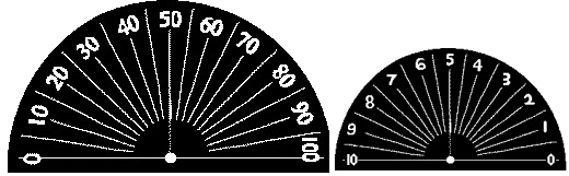 For the dials, you can print these images at a total width of 3 inches, carefully cut them out and paste them on to the front panel under their knobs. Photos of the completed project
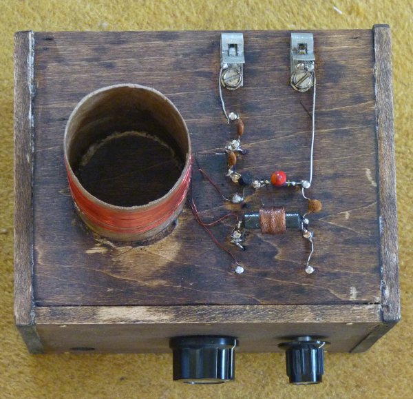 Top deck with the coil and other components mounted. Note that brass nails are driven into the wooden board and are used as termination points. The antenna and ground connections are the clips on the upper right. For old times sake, I wanted to mount the parts on the top deck. There is no reason you can't mount everything inside a box, just be sure your nails (or screws if you use screws) don't protrude through the bottom of the box. 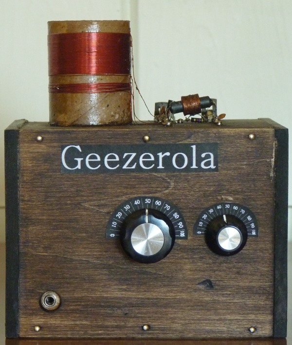 The Geezerola front panel. Station tuning in the center, throttle on the right, phone jack to the lower left. As ugly as this radio is, if you are a boy or girl electrician, 50 years from now you will be very proud of it and you will want to display it in your living room. If you are an adult or geezer electrician, well, maybe you'll want to make it look a little nicer before you show it off. 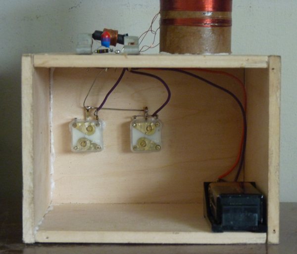 Rear showing the battery and the variable capacitors. The phone jack acts as an on/off switch and is behind the battery holder. 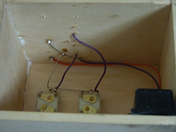 Underside wiring. If you mount everything inside the box, drive the nails in from the bottom and solder to the tops of the nails. An alternative design for the
throttle control
A lady engineer from England has written to tell me that
she built an Armstrong regenerative FET radio that requires a little
more work to build, but looks ever so much better than my radio and
requires no choke coil. She went back to the very early days
of
radio and designed a variable inductor (called a variometer) very much
like those that were used in the days when variable capacitors and
choke coils were rare and expensive. The fact is, most of the
early radios used variometers, so this is a very interesting and
historical version of the Armstrong regenerative radio.
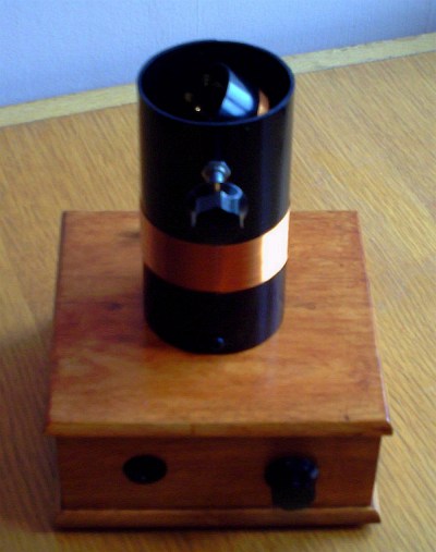 This hansom radio radio has its battery, FET and other circuit elements inside the box while the tuning coil and the throttle's variometer are mounted on top. 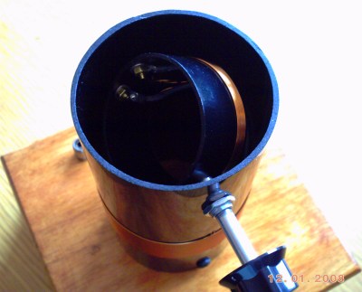 Here is a closeup of the variometer throttle with its control knob. Notice that the variometer is set to about 45 degrees. Now, when the two coils exactly line up, the magnetic field of the one carrying the current will "induce" or couple its magnetic field to the second coil most efficiently, but when the two coils are at a 90 degree angle, very little of the magnetic field is coupled and very little current is created in the other coil. Now, if you had a way to change the angle, by having one of the coils rotate above or within the other coil, you could vary the amount of "mutual inductance" or what is called "coupling" between those two coils. In a tickler coil, varying the amount of coupling is called throttling. A fully throttled tickler coil would be at a 90 degree angle to the main tank coil so that there would be minimum coupling and therefore minimum regeneration (feedback). On the other hand, at some point, as the rotating tickler coil lines up with the tank coil, more and more feedback will occur as more and more signal is coupled from the tickler coil to the tank circuit coil and at some angle, oscillation will start. As you can see, varying the angle between the two coils acts as a very effective throttle and the practical advantage of this is that you don't have to use a choke coil to isolate the tickler coil. Another advantage of the variometer (for us builders) is that they look so interesting and are fun to use, with one of the coils able to rotate about a shaft near or inside the other. Of course, the big disadvantage is that they are much more difficult to build compared to simply buying a small and very inexpensive variable capacitor. The second big disadvantage is the radio must be much larger to accommodate a variometer. With the tiny variable capacitors now available, you can make a radio in the fraction of the space required of a radio containing a variometer. In terms of performance, that is, how well they work to control the regeneration, the variometer throttle is every bit as good as the variable capacitor throttle. 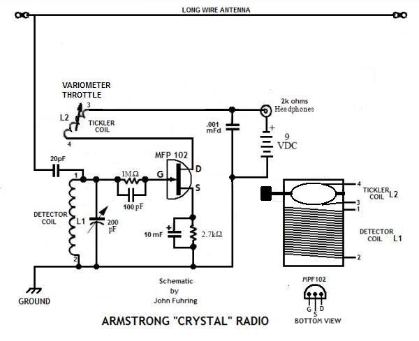 The schematic of my radio showing a variometer throttle The aesthetics (or lack thereof)
of my radio
Compared to the really beautiful works of art that
some crystal radio builders have created, including the one
above,
you can see that my project is crude, really, really crude.
To
show you what I mean, right below here is a picture I captured from Jim
Fredrick's crystal radio site
showing one of his beautiful radios. Speaking of which,
there are some really
beautifully made radios on that site and I invite you to look them over.
 Yes, this is a
beautifully made radio, but even a crude
looking radio will perform well if it uses a good design.. 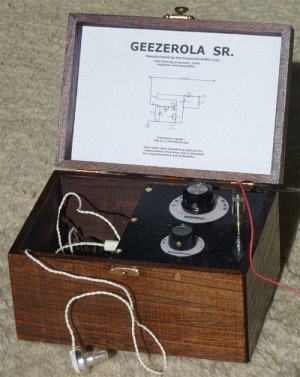 Choosing a "clever"
brand name for your radio
and a little history  The 1921 Aeriola Senior, the first commercial regenerative radio. The first radio station, KDKA Pittsburgh, had begun operation just a few months earlier to broadcast the 1920 November Presidential elections. Only about 500 - 1000 people were able to hear the broadcast, but word quickly got out and caused an instant, nation-wide sensation. The radio station was owned by Westinghouse and this radio was made by Westinghouse. Isn't that a strange coincidence? By the way, one of the reasons the Aeriola Senior is so much larger than my Geezerola Senior is because the tuning coil and the throttle coil are variometers and there are no variable capacitors used in this set. Putting a "brand name" on your radio is optional, but it is kind of fun and you can call your radio anything you wish. The name I chose was "Geezerola" because it is a play on the name "Aeriola Senior" which was the very first one-tube Armstrong regenerative radio to hit the market in 1921. The name 'Aeriola,' meaning "music from the air," was later changed to Radiola in 1922 (probably because the name sounded too much like a certain body part). They were made by the Westinghouse Electric Co. for the newly formed Radio Corporation of America (RCA), which, through their system of patents and ruthless business practices, was to dominate radio design for the next 40 years. If you will look to the point just above the large tuning dial, you will see the glass bulb of one of the very first really good high vacuum tubes to be mass produced in America, the famous WD-11 triode. The radio has a tuning control, just as my radio does, it has a regeneration control, just as my radio does and it has a filament brightness control (upper left) which my radio doesn't need, otherwise the two radios are remarkably similar. By the way, most of these radios were later modified to use the cheaper and more rugged UV-199 tube, but that tube with its adapter base was taller and the lid wouldn't shut. Anyway, I'm sure you can think of a cool sounding name for your radio that you can use to impress people with. How about this: The <your last name here> Aetherola Regenodyne or something equally pretentious that will bring a smile to the faces of those in the know. Of course, you and I both know that the famous Michaelson-Morley interferometer experiment and later Albert Einstein's Theory of Relativity cast serious doubts on the 19th Century Luminiferous Aether theory of electromagnetic propagation, and so it's kind of absurd to call your radio an "Aetherola" (music from the Aether), but how many other people would know that? The
way this radio works is pretty basic
and here's how it all works:
A little more theory
If you read the story of my 1958 Armstrong
regenerative
radio, you will see that the design of this FET radio and my original
radio are almost identical. The only difference is that for
this
radio I am using a "solid state" device (the MPF102 FET) rather than a
"thermionic" vacuum tube (the 1H4GT). The difference between a vacuum tube and an FET You may know that a simple tube like the 1H4 consists of a plate of metal called the anode, a grid-work of fine wire called the grid and a loop of wire called the cathode. In between those elements is nothing, nothing at all because that space contains nothing but a hard vacuum. When the cathode is made hot by passing a current through the wire loop, free floating electrons fill this vacuum and if the anode is made positive, current flows. Between the anode and cathode of the tube there is a grid, as mentioned, and this grid can set up an electric field that controls this flow of electrons very much like a hand valve controls a huge flow of water in a pipe. That is why the English and some other people call electron tubes "valves." When a small, weak signal voltage is placed on the grid of the 1H4 tube, it creates an electric field that greatly effects the relatively heavy flow of electrons between the hot cathode and the anode and thereby it amplifies the weak signal. In Armstrong's regenerative circuit, the weak signal is amplified over and over again as it passes through the tube multiple times. The FET does not have a vacuum in it, rather it has a tiny crystal of silicon. silicon crystals conduct electricity very poorly unless they have been made "dirty" by adding something like phosphorus to the crystal (the process is called "doping"). The doped crystal now becomes a good conductor of electrons just like the boiled off electrons of the cathode makes the vacuum between the cathode and anode a good conductor. Just as the grid of the tube can control the flow of electrons in the tube's vacuum by setting up an electric field between the cathode and anode, the "gate" of the field effect transistor sets up an electric field that causes a "depletion channel" to form in the crystal thus regulating the flow of electrons within the crystal. If the depletion channel is wide and deep, few elections will pass, but if the channel is shallow, lots of electrons will pass. As with a tube, the FET can be configured to take a very weak signal and boost it way up (amplify it). It doesn't matter if you are using a tube or an FET in an Armstrong regenerative circuit, a weak signal is amplified over and over again until the various sidebands and the carrier mixes to produce audio frequency sound that it is loud enough to hear in the headphones. In many ways, you can think of a FET as a very tiny vacuum tube that doesn't get hot, but works pretty much the same as the tube. You can think of a FET as a tube who's cathode (called its "source") is always emitting electrons that flow to the anode (called its "drain") and, as is done by the grid in a tube, the electric field produced by the "gate" of the FET controls this flow. The only big difference is that with an electron tube, there is this big, beautiful and glittering Electropolis to stare into and as your mind's eye wanders through it, your imagination soars. No, FETs are tiny, black plastic things about the size of a booger and about as pretty (you can't even see the crystal), but they work nearly the same as a tube. FETs work as well or better than tubes, are a lot less fragile, use lots less power and will never burn out. Oh yeah, they are a whole lot cheaper and easier to get too. Handsome is as handsome does, I guess, but I do love tubes. The
importance of a good antenna and ground system
Antennas for listening to AM stations
can range
from tiny "loop" antennas that are extremely inefficient, but good
enough for amplified radios, all the way to elaborate "long wire"
systems dozens and dozens of feet long and high up in the air.
The general rule was discovered by Marconi over a hundred
years
ago that the longer and higher the antenna, the better it is at
capturing some of that energy that is passing by. Crystal radios operate only from the energy they capture from an antenna, therefore a good antenna and ground system is vital for their operation. To capture enough passing energy so that it can be processed by a crystal radio's components and then come out as sound energy strong enough to vibrate the mechanism inside the earphone, the antenna needs to be as long and as high as is practical. With this little regenerative radio, because it is ever so much more sensitive than any crystal radio, you do not need an antenna nearly so long and high as you need for the crystal radio. For local stations, a loud signal may be heard using antennas as short as 12 inches and distant stations at night many times come in well with antennas no longer than 10 feet. One thing this radio shares in common with a crystal radio is the need for a ground connection. Right now, I clip my radio's ground to the metal case of a radio that is plugged into the wall and it works great. Water pipes work really well too. The fact is, clipping the ground of this radio to just about any piece of metal seems to work as a ground, even another long piece of wire. Be absolutely certain that you NEVER connect the ground to a hot lead that is carrying AC voltage. Tuning
this radio for maximum sensitivity and selectivity
Of course, this radio, as do
all regenerative radios, can go into self-oscillation if the
throttle is turned up too high (set too far counterclockwise).
Having the throttle set too high produces the infamous squeal
that these radios are so notorious for and which, in the old days,
caused them to be less than popular. The point of adjusting
the
throttle is to make it so the radio is just on the very knife-edge of
going into oscillation. Just before oscillation, just before
the
audio sounds distorted, is when the radio reaches its peak
amplification (best
sensitivity) and when it tunes to its peak sharpness (best
selectivity). You can use the squeal of too much regeneration to your advantage once you learn the tricks. To find a weak station you want to listen to, turn the station tuning knob to a little lower than where you expect to find your station. Turn the throttle clockwise until you hear nothing and then counter clockwise until you first start to hear a faint "rushing" sound. If you tune upward, you will hear stations as whistles and squeals. Zero in on one of the squeals and try to make it as low in frequency as you can (this is called "zero beating") then adjust the throttle until the squeal or distortion just barely disappears. You will notice that if you change the tuning knob clockwise (tuning up in frequency) the squealing will start again and you can't go too far before you have to adjust the throttle clockwise to tone down the regeneration. By going back and forth between the tuning knob and the throttle, you can hunt across the dial for the station you want to listen to, but it is usually best to start low (counter clockwise) and work high (clockwise). Actually, it is a lot easier to learn how to operate a regenerative radio than this description would imply. Learning how to use the regeneration control is one of the fun aspects of this radio and soon you will become expert at it. To get good sensitivity while maintaining reasonable selectivity, I find that a 10 picofarad capacitor works well to couple the antenna to the input tuned circuit. Even with this relatively light coupling, strong local stations might tend to interfere with stations that are near the same part of the dial. If this happens, I suggest you use a short antenna, maybe only 5 feet long, and that way the tuning will be very sharp. I think you will be surprised that even even such a short antenna will still bring in stations quite nicely. By the way, if you change from a long antenna to a short antenna, the tuning will be shifted and you will have to rotate the tuning knob counter-clockwise (add more capacitance) to tune in a particular station. If you change from a short antenna to a long antenna, you will have to rotate the knob clockwise (remove a little capacitance) to tune in that same station. Because the antenna has an effect on the tuning, the dial can't be marked as accurately as a superheterodyne's dial and that is why most crystal and regenerative radios do not have frequency markers on their dial. The
best
time of the day to have fun with these kinds of radios
During the daytime and during the
summer months,
about all that can be received with a little set like this is local
broadcasting. On the
other hand, after sundown (on most
evenings),
electrified layers way up high in the outer fringes of our earth's
atmosphere (the so-called "Ionosphere" also known as the
"Thermosphere")
allow radio waves from far away to be bent
back down to the ground. Under ideal conditions, radio
stations
which are 200 to 300 (sometimes even more)
miles
away may be heard loudly and clearly. This long distance
"refraction" or
bending of the radio waves back to earth (a process called "skip")
makes it possible to hear these distant stations, but it isn't like
listening to the station next
door. This "skipping" of radio waves off electrically charged
layers in the upper atmosphere makes these signals subject to all kinds
of strange things
including interference from even more distant stations, fading in and
out, some odd sounding distortions and sometimes there is even an
echo effect.
These so-called "propagation effects" can be annoying, but if
you
just wait a few
seconds or minute or so,
the signal generally returns. Building
and operating this radio gives insights into science and technology
If you build a
simple regenerative radio like this one, you will learn about
amplification, feedback loops and learn about the demodulation of radio
frequency signals.
You will learn something about the operation of field effect
transistors and tuned circuits. You will learn something
about
antennas and ground systems too. You will learn about how
microwatts
of power can be picked up and heard loudly and clearly due to the
extreme sensitivity of the human ear. In addition to all that, this little radio will provide a motivation for you to learn something about atmospheric physics and solar physics and, if you really want to get into it, a branch of science called "magnetohydrodynamics." By building and operating one of these radios you will hear for yourself the amazing way electromagnetic waves behave at the top of our earth's atmosphere under the influence of our nearest star, the sun. None of this is magic, it is science, but it is so amazing that it almost seems like magic -- the magic of science. I think that listening for yourself, to hear what Nature is doing to these signals way up in the sky, is part of what makes listening to the Broadcast Band at night so interesting. There is a certain randomness to this skip that is explained by solar astronomy and high altitude geophysics. Scientists and engineers all over the world closely monitor our local star and measure it for electrical and magnetic activity. Reports and prediction tables are compiled by various scientific agencies and all this stuff is available on the Internet. You can study and test these predictions for yourself with your radio and by doing so, you are participating in a scientific observation in your own little way. How it all began
This easy to build yet effective radio operates on
the
same principle as the early radios of the 1920s and as I've mentioned,
building it will teach you some important lessons in radio electronics,
but building this radio won't teach you about how radio began.
Radio began in 1865 with one of the most brilliant person who ever
lived, but who today is virtually forgotten. Maxwell, through
his
complex and brilliant equations was able to show that light was an
electro-magnetic wave phenomenon and that visible light was only a tiny
part of the huge electro-magnetic spectrum. This set off a
race
among scientists to see if Maxwell was right and if he was, if anything
useful could be done with these electro-magnetic waves. Except for light, electro-magnetic waves can't be seen or heard, so the first order of business required that they had to somehow be proved to exist and then there had to be devised ways to use them in a practical way. The way to detect the presence of electro-magnetic waves longer than light waves, in the so-called radio spectrum, is with a "radio detector" and so to help to teach you about the earliest radios, I have written a story about the very first really practical radio detector, the coherer detector. In that same essay I also mention how early detectors came and went as radio science progressed. I have a lot of side stories in there too that I hope will give you a more full understanding of how radio got started and what it was used for in the early days. Here and at the end of this article there is a link to my essay on the earliest forms of radio that will give you a good background in basic radio technology: The Coherer and other Detectors used in early radio I think it is important that everybody interested in this sort of thing knows about this early technology and something about the people who made our modern technological world possible through their development of radio science. How
far we have come
Exactly 100 years ago Edwin Armstrong
used an
expensive and unreliable Audion
triode tube in his first radio. Armstrong's design didn't
catch on
at first, but his ideas set
the stage for
many great advancements in radio. Ten years later in 1921,
when
my
mother was a young girl, everyone was eagerly listening to this
wonderful new entertainment and almost everybody was listening with
crystal sets, but
just ten years later, the crystal sets were gone, replaced by powerful
vacuum
tube radios that were able to bring in stations from all over the
world.
In a
relatively short span of time, the time since my grand parents were
young in the 1890s to my parent's time,
to this very moment, consider just how far we have come with
radio, television, GPS, cell phones, satellite broadcasting, wireless
Internet, interplanetary missions to space and so much other allied
radio technology. Consider too that it all started with
simple
little radios very similar to the one this story is about.Conclusions:
People love to build simple radios and
they are a
lot of fun to get working, but let me say this right now, if you are
going to go
to the bother of winding a coil and putting together a
little radio, you will want performance that makes the effort
all worth while, so please don't bother building an "ordinary" crystal
radio. Do yourself a
favor and build this little radio. You will have something
that
goes together quickly, uses only ordinary parts and works hundreds of
times better than anybody's crystal radio. To top
it all off, you can do nighttime Broadcast Band DX'ing without
the
huge outside antenna that a regular crystal radio must have. By the way, just recently, I compared the performance of this little FET radio with my 1958 vacuum tube radio. Both radios were connected to a short antenna only five feet long. I was surprised that the performance of both radios were nearly identical in every respect. In the evening I could pick up and listen to KGO in San Francisco (200 miles away) equally well. When I experimented with the two radios several days earlier I thought the FET radio was superior because it seemed louder when connected to the long wire antenna I use for my crystal radios. Actually, using an antenna that long with these radios is not a good idea and they actually seem to work better with much shorter antennas. To any young person reading this, let me say that any little radio you build should be something you are proud of showing to others and it should be something you will proudly display (and maybe even write an Internet story about) 50 or more years from now. I sincerely believe that this little Armstrong "crystal" radio is just such a project. In my opinion, it is a worthy successor to the Boy Electrician radio I built in 1958 and of which I am still very proud. Why you might want to have second
thoughts about building this radio
(These are my personal opinions that you are not obliged to agree with and you may skip down if you wish)
There is something that should be considered
when thinking about having your young people build any kind of AM radio
and what I'm referring to is the unpleasant realization that,
in many
places in the U.S., there is absolutely nothing on AM radio that is (in
my
opinion) good for young, developing minds to listen to. Many
local
broadcasters pander to the most disgusting right-wing propaganda and
Fundamentalist religious crap. Anyway, it is my opinion that
persons
wishing to direct
young people into building a simple AM radio should carefully monitor
their local AM broadcasting for the kind of trash I'm taking about.
If
the local airwaves are full of this trash, they must ask themselves:
would
building this kind of a project likely help or
harm their young people? I think building an AM radio can
have the
potential
to do more harm than good if your area is dominated (as mine is) with
this sort of trash broadcasting. Now, on the other hand, if
you
actually WANT your kids to be exposed to religious or political
propaganda before before their minds are sufficiently developed to
resist brainwashing, then ignore this warning.
Of course, this applies to adults wishing to build one of these radios too. Is it really worth the expense and especially the effort to build a crystal radio when there is nothing to listen to? I did it strictly for the technical challenge, but certainly not to listen to local entertainment. All this aside, if you decide build this radio, I think you will have a lot of fun and will learn a lot. Just remember that for about the same money you can get a MP3 player with an FM radio and 8 gigs of memory. While the MP3 player is a better deal, listening to it won't teach you anything about electronics. However, the horrible trash that's on AM radio has a well deserved reputation for making its listeners stupid and crass while listening to classical music through your MP3 player just might make you smarter and highly cultured, but it's your choice. The best use I have found for my Armstrong "crystal" radio is to spend a few minutes at various times of the day and night (especially at night) listening to see what distant stations are coming in. I listen just long enough to discover where a station is because it's fun to monitor the condition of the "skip" off the Ionosphere, but that's all I'm interested in. I sure am NOT interested in their programming. Now, having said all that, locally we have two strong Mexican music and call-in stations near the top of the dial. Those who understand Spanish and like Mexican music would really enjoy using this little radio because of this. I tune those stations in from time to time because sometimes it's fun to listen to polka music or chuckle at the extremely maudlin lyrics of some obviously heartbroken singer. Even though I don't speak a word of Spanish, sometimes it is pleasant to listen to how polite the radio host is to his call-in listeners and how he lets them do all the talking without haranguing them politically. I only wish the English language AM stations had such polite hosts who aren't filled with all this right-wing and conspiracy theory, hate-talk and don't have to be telling everybody all day and all night long about how hateful their idea of their god is. Some final words
Can a radio such as this be modified to operate on
the shortwave bands? Of course it can. To tune to
the
higher frequency shortwave bands, all you have to do is use fewer turns
on the two coils, especially the tuning coil. If I see that
there
in much interest in a shortwave version of this radio, I'll include
instructions for winding coils with fewer turns, but until then, you
can experiment for yourself. One really effective and easy
way to
adjust the turns on your tuning coil would be to connect a frequency
counter to the antenna and ground, put the throttle into oscillation
and read the frequency. Adjust the number of turns of the
tuning
coil until you are in the band you want to be and adjust the tickler
coil until the throttle works smoothly. Believe me,
experimenting
like this is a lot of fun.
By the way, if you build a radio based on what has been presented here, please drop me a line and describe it to me and, if you can, attach some pictures. I'd sure appreciate it if you would tell me how much you like the radio and how it performs for you. You can write me directly at my geojohn.org mail address. Good luck. The End Having
arrived this far,
obviously you have a superior attention span and reading ability that
far exceeds that of the majority of web users. I highly value
the opinion of people such
as yourself, so I ask you to briefly
tell me:
Did
you enjoy this article
or were you disappointed?
If you have any detailed comments, questions, complaints or suggestions, I would be grateful if you would please E-mail me directly You might like to
read the story of my Armstrong regenerative radio
that tunes shortwave and uses an FET for the detector,
 My Regenerative Shortwave Radio. or perhaps you
would like to read the article on
 The Armstrong regenerative radio I built in 1958 If you are looking to build something with the same great performance of these little regenerative radios, but looks a whole lot nicer, I would like to suggest  The Geezerola Senior radio For more background on how early radio got started and evolved, perhaps you would like to read my essay on 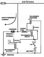 The Coherer and other Detectors used in early radio I have written a little essay you might like that explains some of the principles behind 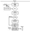 How The Armstrong Superheterodyne Radio Works | ||||||||||||||||||||||||||||||||||||||||||||||||||||||||||||