My First Amplified Radio Project based on the Armstrong regenerative principle with detailed notes on what lead up to building it A comprehensive story containing historical, educational, technical and biographical elements & my opinions by John Fuhring
My introduction
to the magic of radio science
I can remember exactly when my interest
in
radio
technology began.
In 1955, when I was turning 10 years old, my wonderful aunt
Helen
sent
me a birthday present. Inside the box was this outlandish
collection
of wire & other hardware including a rock crystal, a small
"cat's whisker" mechanism,
a
wooden coil form, a Bakelite chassis for
mounting everything and a
set of rather nice headphones (that I still use). It also
contained a sheet of instructions
on
how to wind the
coil, how to mount everything in the chassis and how to wire all the
parts together.
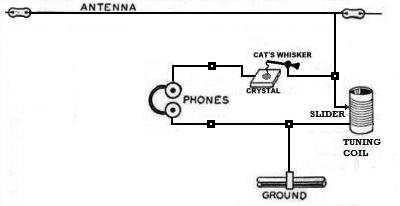
 My first crystal radio in its Bakelite chassis. I was searching the Internet for old crystal radio kits and good lord, there was a picture of my radio just as I remembered it.
In addition to all the parts, the box included printed instructions on how to string up an antenna wire in a tree and how to establish a ground using a steam radiator or water pipe. In addition to all that, there was an illustration of how radio waves travel from a station and how these waves are captured by the antenna as they pass by. The sheet went on to explain how these waves are turned into electrical currents by the antenna. It told me that the different radio stations are then separated from each other by the tuning coil. Finally, there was an explanation of how a radio current, that is impossible to hear, is turned into electrical sound waves by the crystal and cat's whisker and then how those electrical waves cause the electromagnet inside the headphone to make the headphone's iron diaphragms vibrate and it was these vibrations that made the sound. I don't know where or how I knew some of this stuff, but I had already been exposed to bits and pieces of electrical theory and electromagnetism, so putting it all together this way made sense to me. For all this explanation, I still couldn't understand how anybody could call this collection of wire, rocks and other junk a radio? Naturally, I was familiar with radios and as all people did back then, I avidly listened to news, comedy, music, drama and adventure programs that filled the AM radio waves. But, but, BUT, all "real" radios had these glass tubes in them, tubes that you could see the insides glowing red hot if you looked around the back. What is more, I knew that radios worked on electricity and they had to be plugged into a wall socket or no sound would come out. Now, here in this box were the parts of something called a "crystal radio," but there were no tubes, no batteries and no power cord. Looking at all these inert parts - wire, screws, wood, Bakelite plastic and a piece of rock - I was extremely skeptical that anything so simple could possibly be used to hear radio programs. My mom (born in 1909) assured me that when she was a girl, many people in her town in rural Pennsylvania made these little radios and with them they would spend their evening hours listening to the big stations in Pittsburgh and Albany. My mom knew everything, so I put aside my skepticism and decided to build this thing. My first attempted to build the kit and get it to work was a failure because I didn't understand the importance of winding the tuning coil neatly and I got some of the interconnecting wiring wrong in my haste to put it all together. When I complained that couldn't hear anything, my mother pointed out that my workmanship was really poor and of course it wouldn't work looking that sloppy. It was obvious that she was right, so I got out the sheet and this time I put it together according to the diagram. I rewound the coil, but this time all the turns were regular so that the antenna slider could now move smoothly from side to side. As per the instructions, I took some sand paper and carefully sanded the varnish off the top of the coil so the slider would make contact with the wires. I took the interconnecting wiring out and then carefully rewired it exactly the the way the diagram showed. When I was done, I was pleased to see that my radio now matched the instruction sheet perfectly. The lessons in craftsmanship that I gained from building this radio were good and early lessons that have served me well since. If you want something to work, you must build (or repair) it right. Confident in my workmanship, but still feeling skeptical, I placed my radio on a little wooden shelf above my bedroom's radiator. I then connected the end of the antenna wire (that I had placed up in a nearby tree per instructions) to the little "antenna" input of the Bakelite chassis. My bedroom's steam radiator had a bright chrome-plated vent valve, so I connected a wire from the radio's "ground" connection to it. I could almost hear a drum roll as I put on my headphones. Silence -- I could hear nothing in my headphones -- so I moved the slider from one side to the other, but still silence. At this point, I learned another principle that has served me well all my life and it is just this: "when all else fails, read the instructions." The instructions said that I had to find a "hot spot" on the crystal by moving the tip of the "cat's whisker" over the crystal until I could hear sound. Well OK, I made a connection between the tip of the whisker and the surface of the crystal and then tried moving the slider again. I was absolutely stunned when I could hear sound in my headphones and the sound got louder as I moved the cat's whisker and found a better "hot spot" on the crystal. How could this be possible?? Here I was, hearing voices and music coming out of mere wires and doing so with no tubes, batteries or house current to supply electrical power, but that was impossible. I mean, even back then I knew that Nature does not give you something for nothing, so where was the power to create these sounds coming from? I was extremely impressed and although it seemed like a miracle, I knew it wasn't supernatural, but rather it was a "miracle of science" and so I wanted to know all the mysteries behind how this stuff worked. Because the radio was made up of ordinary things, I felt confident that I would eventually understand how all these parts combined to do what seemed to be magical things. The tuning coil I made up myself out of ordinary copper wire and it was wound on an ordinary piece of wood, the cat's whisker mechanism was made of ordinary pieces of metal and the crystal was just a shiny piece of rock. When I unscrewed the cap on the headphone, I could see the iron diaphragm and the coil of the electromagnet inside. Although it seemed like magic, it wasn't magic and I was sure that it wasn't beyond my ability to understand how it all worked. It was immensely pleasing to see (and hear) how I could take ordinary things and make them do something so wonderful. This was the beginning of a life long fascination with radio and electronics that has continued (off and on) to this day. I made several improvements to my original crystal set including replacing the big "cats whisker" with a bead of glass that had a tiny crystal with a tiny cats whisker inside, but that actually worked a whole lot better than even the best big cat's whisker. Looking back, I wonder that I was able to keep my interested in radios alive during this period because neither my parents or teachers encouraged me in this and none of my friends had the slightest idea how radios worked, or shared my interest in anything so "square" (or "nerdy," as we'd say today). My parents and teachers considered all these wires and batteries as a pernicious distraction from my otherwise neglected academic work and prejudicial to my social development. Perhaps they were right, but a nerd will be a nerd, a Dilbert will be a Dilbert, there is no other way we can be, and, as it turned out, my hobbies did more for me in my later life than any of the "book learning" that my betters forced on me. So, I continued to want to know more about radios, wires and gadgets and to teach myself what I could about all that stuff. I'd like to take a brief digression here and I hope you don't mind. I found out later that making and listening to these simple radios was a craze back when my mother was a girl and their wide-spread use starting in the early 1920s was largely responsible for getting early broadcasting started. I don't think it is a bit of an exaggeration to say that these were the I-pods of my mom's generation and it was these simple devices that even poor people could afford that started engineers and scientists looking for better and better ways to receive radio signals. This untiring search has resulted in the world of electronic communication and entertainment we have today. More
crystal radios
By 1957 we were living on the hospital side of Camp
Pendleton Marine Base and I was in the 7th grade. By this time,
the crystal radio bug had really hit me and I experimented with
improved crystal detectors. I discovered that the
little glass 1N34 diodes worked better than any cat's whisker and the
Marine Corps hobby shop sold them. While playing
and experimenting with crystal sets and diodes, I heard about
these little things called transistors that were just becoming
available. My folks knew what interested me, so they bought me
another little crystal set for Christmas, but this one had a one
transistor audio amplifier in it and it was so cool looking. This
radio
worked really well and it was the center piece of a radio corner that I
set up in a
little "fort" that some of us kids built out of wooden crates and
large boxes that we
salvaged from the Marine Corps' military dump. Unfortunately,
there
were no trees around, so my very poor antenna system consisted
of military field telephone wire laid along the ground and in the sagebrush. It so
happened
that the tuning of this little radio was so broad, I could hear
some of the military shortwave broadcasts the Marines made while
on maneuvers on other parts of Camp Pendleton.
I just loved it.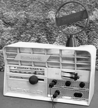 My Remco crystal radio with a transistor amplifier. Well, in 1957,
transistors were still mostly curiosities and very, very expensive.
Transistors were also tiny and their workings were hard to
understand. At that time in history, the next step for a boy
learning
about electronics would naturally involve electron tubes (sometimes
known as vacuum tubes, valves or simply as tubes).
Electron
tubes
I
really began
to learn
something about radios and how amplifiers worked when, about age
13, I built the one tube regenerative
receiver I will shortly describe. Children of my generation were
quite familiar with tubes, we all knew that tubes were what made radios
work and that sometimes tubes "burned out" and had to be replaced.
Yes, we all knew
about tubes, but I
wanted to know what all those things inside were and what made those
tubes work. The wonderful thing about tubes is that they are built to a macroscopic scale. When I was a kid, I would look long and deeply into tubes, let my imagination soar and see a fantastic, glittering, futuristic city inside that glass envelope. I could look inside the glass and into that vacuum filled Electropolis and identify each glittering element. I could break open old tubes to examine their contents under a magnifying glass and see that they were nothing more than thin strips of metal or wire. Even a kid like me could see and identify the 'cathode,' the 'heater' wires, the wire spiral that made up the 'grid ' and the thin metal 'plate' (or anode) that encased everything. By seeing all these parts and holding them in my hand, I could imagine electrons "boiling" off the hot negative cathode. I could imagine how they would be attracted to and picked up by the positively charged plate (anode) and how that flow could be modified by tiny voltages on the grid wires. It was an easy step imagining how tiny voltages appearing on the grid would be amplified into large plate currents that would run the powerful electromagnets of a speaker. A visit to the magical city of Electropolis
Speaking for my fellow nerds, I will say that there are few
precious jewels that
look so beautiful as a big,
old fashioned, glass vacuum tube containing within it a glittering
Electropolis. These futuristic looking "cities in a bottle"
were manufactured up to 75 years ago using technologies that, to this
day, most of us don't understand and have no experience with, but
nevertheless, they are existing unchanged and
unchangeable, preserved forever behind a thin, transparent glass capsule that preserves their nearly
perfect vacuum. Within any one of these tubes, between the glittering elements, across the ultimate emptiness of the vacuum inside, flow invisible and complex streams of electrons that no living creature may see. The passage of electrons are invisible, but fortunately our mind's eye has the power to "see" things our mortal eyes can't see. With a real sense of awe, I sense the truth that tiny, almost massless, subatomic charged particles people call electrons are making their highly regulated journey through this vacuum at nearly the speed of light. In school and through our textbooks, you and I were taught - and we can readily believe - that this "electric fluid," this plasma of charged particles, is moving under the influence of a high voltage electric field, but that the movement is made possible only because the cathode is red hot. Again, our mind's eye "sees" a cloud of electrons that has been "boiled off" the metallic cathode through that wondrous process called the "Thermionic Effect." What is more, we know that this flow of electrons between a tube's elements can be and is precisely regulated by tiny electric charges that make their way to that spiral of gleaming wire called the grid. We know that all this scientific magic is true because we built the radio ourselves, we connected our high voltage 'B' battery to the anode and cathode circuits and we are using current from our 'A' battery to heat the cathode red hot and make it boil off electrons. We know that this isn't "just a theory" constructed by people learned only in magical and superstitious thinking but is instead a Scientific Theory constructed by people highly learned in the complexities of real world science. Each of us can see into the very heart of the tube and we can hear music and voices in our headphones so we know all this is happening, but you and I can only experience this kind of epiphany to its fullest degree if we have a vacuum filled tube with its glittering Electropolis to stare into. Back home on my side of the glass
As a first lesson, I learned that vacuum tubes
operate on that almost forgotten
principle called the
"Thermionic Effect" that I mentioned above. This principle is so
important, I want to say more about it. Way back in the 1880s
researchers
at
the
Edison
Laboratories in
New Jersey (not Edison himself) discovered that some kind of an
"electrical fluid" (later found to be electrons) "boiled off" hot
filaments, but in a one-way direction (from the cathode to the anode).
Later, John
Ambrose Fleming used this
principle to
produce an improved diode tube (the famous Fleming Valve) to detect
radio waves. At the time, this was the best detector there
was.
It was thousands of times more sensitive than the coherer
detector in use at the time and it actually worked better than the
crystal diode which came a little later. Of course, the crystal
detector was much, much cheaper, required no battery, lasts
forever, is very rugged and so crystal detectors with their annoying cat's whiskers superseded the Fleming Valve for a
long
time until it made a comeback in an improved form about 20 years later.Warm tubes and cold transistors
By the
way and this has nothing to do with the present discussion, later on,
when I started to experiment with
transistors, it
was
impossible for me to see inside them and so it was much harder for me
to
imagine
"holes"
moving through a crystal lattice. The truth is, I've never had a
"warm feeling" for transistors and integrated circuits, regardless
how marvelous they are. No, but I've always had a kind of
affection for tubes.The first thermionic vacuum tube radios
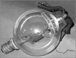
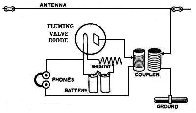 A Fleming Valve Detector Radio. Very similar to the crystal detector, but generally more sensitive. The Fleming Valve was superior to the crystal detector, but consumed expensive tubes and batteries. In 1907, Dr. Lee De Forest added a third circuit element to a modified Fleming Valve tube to make a (very expensive and unreliable) crude forerunner of the triode tube, called the Audion. To get around Fleming's patents, De Forest left a lot of gas in his audion tubes so that they operated in a very poor vacuum. De Forest then claimed that it was positive ion migration that made his tubes work. In 1912, while still an undergraduate in college, a very young Mr. Edwin Armstrong wrote a paper that proved De Forest was completely mistaken regarding the internal operation of the Audion and indeed De Forest really didn't have a clue how his tubes worked.* In hindsight we can say the Audion was a crude device, but it was an important start and it soon evolved into the linear amplifying high vacuum triode tube through the work of other researchers.
A better kind of radio
For the first two decades of the 20th Century and all through the Great War (WW1), almost all
radio receivers used a diode detector (a crystal or Fleming Valve).
Now it is true that in 1911, Edwin Armstrong
developed a better way of detecting radio waves, but his radio required
a rare and expensive high-tech device (the Audion
tube) and it needed two batteries in order to work. Armstrong's
new radio was almost as simple as a basic crystal radio, but
it could bring in weak, distant stations and it could separate stations
that were right next to each other far better than even the best crystal
detector radios and even better than De Forest's grid leak detector radios could. A little history As obviously superior as it was, Armstrong's radio wasn't much of a success at first because high performance, reliable and affordable triode tubes hadn't been developed yet. Add to that, World War One came along at just the wrong time and besides, there were no radio stations broadcasting entertainment programs for people to listen to. Because of these factors, the regenerative radio principle went unused for several years. Speaking of good triode tubes, I think that it is ironic that they were first produced as early as 1912, but by law they were not allowed to be used in radio equipment. Nevertheless, it didn't matter because World War One put a stop to civilian radio development. In fact, ordinary Americans weren't allowed to even own radio equipment until after 1919. During the war, American triode tubes (developed by Western Electric) made their way to France, from France to England and from there back to America so that with end of the war, everything was in place for the birth of The Radio Age. Around 1920, there were finally some radio stations on the air using powerful newly developed transmitting tubes and the number of stations on the air grew very rapidly. Just as importantly, there were finally some really good receiving tubes (like the WD-11 triode) for sale at more or less reasonable prices. It was these new triode receiving tubes that made Armstrong's regenerative radio a success. By the mid 1920s, people began to abandon their crystal radios in favor of tube radios, but not all at once. As desirable as it was to own a tube radio, they and their batteries were pretty expensive and many people just couldn't afford them, so crystal radios remained popular with the public until the mid 1920s. After that, almost nobody listened to the radio with a crystal set anymore, however, in a very limited way, crystal radios have remained popular with a few of us experimenters and kit builders to this very day. By the early 1930s, Armstrong's regenerative principle lost the popularity it had enjoyed during the previous 10 years as regenerative radios were replaced by superheterodyne radios. Now wouldn't you just know it, the superheterodyne was invented by the same (then Captain) Edwin Armstrong during World War One while he was in France working on radio direction finders for the U.S. Army. The superheterodyne is a marvelous invention and, to this very day, nearly all radios are based on the superheterodyne principle. As with the regenerative radio, the superheterodyne wasn't popular at first because it too had to wait until improved tubes were available to make it practical. Just as the WD-11 triode tube made the regenerative radio practical, wonderful new tubes such as the 35 and later the 6A8 made the superheterodyne practical. So, like the crystal radio before it, technological change caused the regenerative radio to loose its popularity with the general public. However, because of its amazing simplicity and excellent performance, the regenerative radio has remained popular with a few experimenters and kit builders to this very day. I should mention that Armstrong's regeneration principle became obsolete after 1930, but only here in America. In the 1930s, wages in Germany were extremely low and people didn't have a lot of money to spend on a radio. However, the Minister of Nazi Propaganda, the evil Joseph Goebbels, was keenly aware of the value of AM radio as a propaganda tool (as the political and religious Right Wing is today here in America) and so, under the direction of the Nazi government, a line of simple, affordable, but good performing radios (called Volksempfangers) were manufactured. Unlike the American radios of the period, the Volksempfangers had no shortwave and indeed, it was strictly forbidden to use them to listen to foreign broadcasts. As simple and inexpensive as they were, they still cost the equivalent of over $1,500 in today's money. Produced from 1933 to 1945, they were probably the last mass produced radios who's design was based on Armstrong's regenerative principle. How I
built my Armstrong regenerative radio
I am no Edwin Armstrong and when I was
a kid, I knew almost nothing about radio circuits, so I must admit that
I didn't come up with my
radio on my own. I got the plans for my Armstrong regenerative
radio from a wonderful book of science projects called "The Boy
Electrician" by Alfred Morgan. The first edition of this
book came out as early as 1913 and was updated every few years with my
copy printed in 1940. Much of the technology in the book was over
50 years old even then, but it was full of good, basic science and many
of the projects were something a kid could build and learn while doing.
One of the projects was an elaborate, but old fashioned crystal
set that looked difficult to build, but the project that really
appealed to me was a one tube Armstrong regenerative radio. In the early 1920s, the first hand blown tubes and factory-made regenerative radios (such as the Arieola Senior) were still very expensive, however these little radios began to become very popular and many young people built them from kits and from a series of wonderful plans published by the U.S. Government. Making one of these radios at home could save a person a lot of money because, as I mentioned, factory radios were so expensive. However, by the time I built my little radio things had completely turned around. The fact was, I could have easily bought a used five tube factory built AM radio for less money than what I spent on parts for this little radio and I wouldn't have had to spend any time building it. Nevertheless, this one tube radio was something I could build myself and something I could learn from so the education I got and the satisfaction I received was priceless. God knows that I wasn't learning much in school, so I needed to learn something. For parts, I bought some of them new, but the headphones I reused from the original crystal radio my aunt Helen gave me. The 1H4GT triode tube, the carbon resistor, the sockets, the potentiometer and the silver-mica capacitors I bought at the Sears Warehouse that we used to have here in town and where they repaired Sears "Silvertone" radios and record players. I remember the clerk wondering what in the world a dumb kid like me wanted with one of those 1H4 tubes, which were pretty old fashioned by then and they only had one of them in stock. I also remember how amused the guys behind the counter were when I asked for "two, two hundred and fifty micro micro farad CONDENSERS." Even by then, the word 'condenser' had gone out of style. The tuning coil was another matter. The book called out "standard" plug-in coils, but nobody had them or had even heard of them -- they must have been for some very, very old radios. There were plans for winding your own coils, but I couldn't get or make the coil forms so I had to wind my coils on an old toilet paper tube (which is now falling apart and I had to 'dope' back together). By the way, I wanted to use this radio to listen to shortwave in addition to the broadcast band. Just as I had made my own broadcast band coil, I intended to make up additional coils for the shortwave bands, but I never made those coils because I couldn't find any more plugs for sale in town. Nevertheless, there is no reason why this radio would not work up on shortwave, so maybe I'll try to find plugs that will mate with my socket and wind some more coils for my old radio as I had originally planned to do so long ago. One of these days -- maybe. I didn't have the tools or the experience or the skills to build this project the way it was pictured in The Boy Electrician, but I came up with a way of building it using what skills and materials I had. I picked out a nice piece of pine panel, left over from a nearby house under construction, to be the main chassis. On that board I mounted the tube and other components as shown below. To make a box for the batteries under the chassis board, I sawed and nailed up some left over pieces of redwood fence boards. It was really crude and really ugly as you can see, but I was just a kid without any tools or any expert help. Here is what it looks like today: 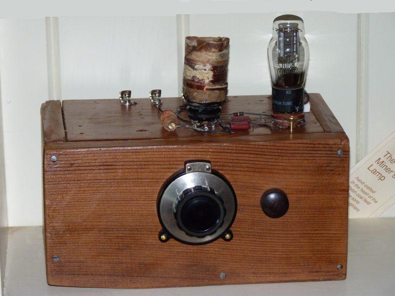 Main tuning control in the center, regeneration control on the right. The large gear drive vernier tuning dial was added recently replacing the large knob I originally used. The small knob to the right is the regeneration (throttle) control. Originally that knob operated a potentiometer as the throttle, but now it controls a variable condenser. Isn't that big glass tube absolutely beautiful? 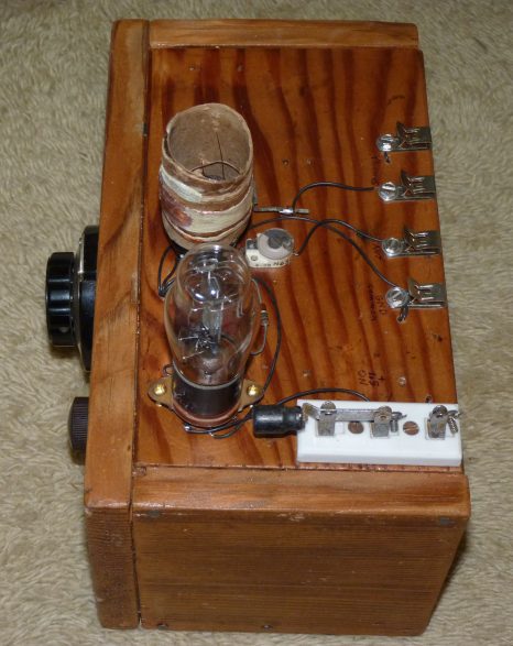 On/off switch, antenna, ground and phone connections. You can look right down inside the Electropolis and see all the gilttering elements that makes up the thermionic tube that is the heart of this radio.  Rear showing the "battery box," Not
exactly an Atwater Kent, but
pretty good for a 13 year old kid.
You know, I'll bet I was the only kid in town who made one of these radios and I am still proud that I made it without any adult encouragement or help. Today I live in a small city, but way back in 1958 Santa Maria was just a large town. Nevertheless, just about everything could be had locally and in many respects, hardware and even electronic parts were easier to get back then. Today all the local merchants have been put out of business by huge mega corporations owned by faceless boards located god-knows-where and today my town's stores only carry those Chinese made products that are quick selling and pre-manufactured. Indeed, all the "hobby shops" in town closed their doors years ago and it is nearly impossible to get those kinds of items anywhere in the region. Of course, there is the Internet, but it was so much easier and so much fun to simply walk into a well stocked hobby shop, look around and let your young creative juices flow. Before I leave this topic, I think I need to say something about how I powered this little radio. All vacuum tubes require a hot cathode to "boil off" electrons and most tubes have a cathode that is indirectly heated. An indirectly heated cathode can operate on AC which means that the radio doesn't have to have a battery to heat the cathodes, however indirectly heated cathodes require a lot of heater power and are not suitable for battery operation. The 1H4 tube was designed for low power operation so its cathode is the filament and because of that it operates at low current (only 15 milliamps). Because the 1H4's filament requires so little power, I could operate the filament for many hours using one of those huge "telephone" cells (called an 'A' battery) that were so common back then. Today I use a single 'D' cell and it lasts at least as long as the old telephone battery used to. In 1958, to power the plate circuit of the 1H4 tube, I used a small (and what was then a commonly available) 45 volt portable radio battery (called a 'B' battery). These batteries haven't been made in 50 years, so to make my old radio work again, I made up a 'B' battery by ganging together five 9 volt batteries until I had 45 volts. A
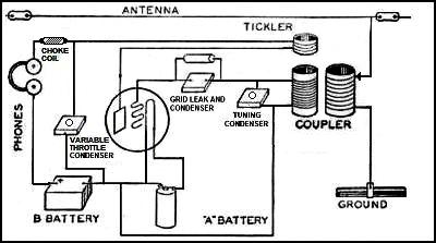
technical discussion of how an Armstrong Regenerative detector works
To pick up radio signals, a piece of wire has to
be
strung up
as high and as long as practical and some kind of a ground must be
connected too.
Passing
radio waves from a distant transmitting station electro-magnetically
couple to this wire and,
in response, a very tiny, but high frequency electrical voltage
appears on the wire. The frequency is so
high
that the signal passes through the Trimmer capacitor and
starts a alternating current flowing back and forth in the coil between
points G
(and the top of the tuning condenser) and point C (and the bottom of
the
tuning condenser). That tiny high frequency alternating
current
is then coupled through the "grid tickler" network consisting of a 2
meg resistor and the 250 mmfd capacitor (to the right of the
coil/condenser) and from the "grid tickler" the signal appears on the
grid, pin 5 of the 1H4 tube. (Note: this discussion assumes you know something about resistance, capacitance, inductance and tuned circuits. If you slept through science class, you may wish to skip this section.)
The "regenerated" signal that is magnetically coupled to the main tuning coil is coupled to the grid of the 1H4 through the grid tickler network (250 mmfd capacitor & 2 megohm resistor) and the signal is amplified again. This goes on and on and, depending on how the regeneration control is set, the overall amplification may be several hundreds or even thousands of times the original signal level. Amplifying a signal over and over again like this would be just great, but this kind of amplification (called "positive feedback") can easily be overdone and you don't want to over do it. It is of utmost importance that the amount of "positive feedback" (regeneration) be set very carefully. If the throttle is set up too hot with too much bypassing to ground, the tube will go into self-oscillation and a squeal will be heard as the original radio signal "heterodynes" with the oscillation of the tube. On the other hand, if the throttle is not set up hot enough, the tube doesn't amplify very well. Finding that elusive "sweet spot" of just exactly the right amount of regeneration is why a smooth throttle control is necessary. If you will look at the upper left of my radio's schematic above, you will see something labeled '2.5 mH CHOKE COIL.' A choke coil blocks high frequency radio current, but allows audio frequency current to pass through. A choke coil must be used here or the bypassing will be very chaotic and the regeneration level (throttle) will be very unstable or it won't work at all. During all this amplification going on inside the tube, the parts of the original radio signal (the carrier wave and the audio sidebands) are all mixed together (or heterodyned) and audio frequency currents are produced. This audio frequency current passes through the choke coil and from there, the current flows through the electromagnets in the headphones, those currents cause changes in the magnetic field that attracts the iron diaphragm of the headphones causing them to vibrate and it's those vibrations that I hear as music and voice sounds. An alternative and the older way of looking at how the regenerative detector works is called "demodulation by grid rectification." The way this is supposed to work is as follows: the radio frequency wave, that has been amplified by regeneration, has, by the nature of it being an AC wave, positive and negative components. These components vary in strength in step with the audio wave that was superimposed on it when it was originally transmitted by the radio station (see the diagram below). When the radio frequency wave with this audio wave superimposed on it reaches its maximum positive voltage in the tank circuit, it also reaches its maximum value on the grid of the tube by being coupled through the grid tickler network(1 megohm resistor and 100 pF capacitor) -- supposedly by "charging" the 100 pF capacitor. Electrons from the hot cathode are attracted to the now positive grid and current flows, but an even greater current flows between the cathode and the anode. When the radio frequency wave turns negative, current flow between the grid and the cathode is cut off and this cuts off the current flow to the anode too. This creates a very rapid series of current pulses across the tube that vary at the radio frequency rate, but create an average current flow at the audio rate. When these varying current pulses are smoothed out by going through the choke coil and the bypass capacitor on the other side, an audio frequency wave results and may be heard in the headphones. In this way, the modulated radio frequency wave appears to be "rectified" as if it was going through a crystal or Fleming Valve diode, but because this current flow is greatly amplified by the enhanced current flow between the cathode and anode, the audio signal is likewise greatly amplified. 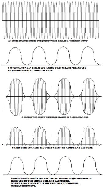 Audio and radio frequency waveforms used by or produced by a regenerative detector. The
importance of smooth control of the regeneration
To control the amount of
regeneration, you
need a way to carefully increase or cut down on how
much
radio frequency current is flowing in the tickler coil. Too
much
current and all you get is a squeal, but too little
current and you don't hear anything. This is called
"varying
the amount of bypassing" and you have to have it set exactly right for
best
performance. In the real old days of radio, this regeneration
control was called "the throttle circuit" because they "throttled"
the regeneration up and down just like you controlled the speed of an
car's engine by its "throttle" control. For throttling in the old
days, they always used a variable capacitor.
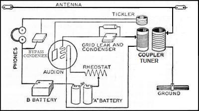
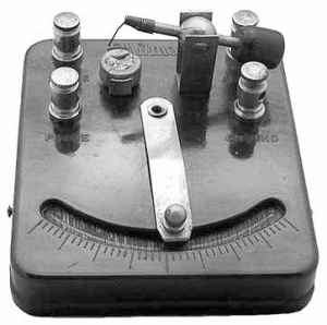
 Typical Regenerative Radio of the 1920s. A variable "throttle " condenser was a common and excellent way to control the amount of bypassing and thus control the amount of regeneration. 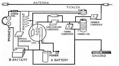 Original Regenerative Radio Design from The Boy Electrician. The amount of regeneration was "throttled" by a rheostat across the tickler coil. This proved to be very difficult to control and so I came up with a better way on my own. Well, at the time I built my radio, variable capacitors were expensive, hard to get and hard to mount, so a variable capacitor to control regeneration was out of the question. As suggested by the book, I used a rheostat to "swamp" the tickler coil and control the regeneration that way, but soon discovered that this method worked very poorly and the right amount of regeneration was just about impossible to control. I then came up with what I thought was a very clever idea. 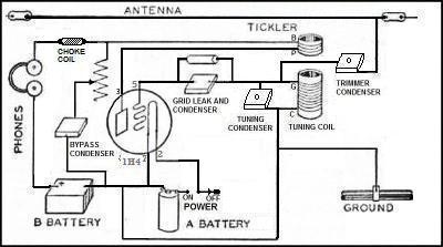 My
radio with its modification
as it would have
appeared in The Boy Electrician.
May
26, 2011. I
make
an important discovery after only 50 years.
.
I have a confession to
make. Yesterday I modified my first radio and now it isn't
exactly the same as when I built it so many years ago. I had
to
because facts came up against my pride and the facts won.For the last several evenings, I have been "DX'ing, " on the broadcast band to see just how well my old radio performs. I originally discovered the defects in the design of the Boy Electrician's regeneration control by spending time with it and becoming dissatisfied with its performance. By recently spending time searching out weak and distant signals, I once again became dissatisfied with my radio's performance. While my throttle control method is a vast improvement over the Boy Electrician's method, it has its own defects that I finally decided needed addressing. While trying to tune in weak stations, I noticed that the tuning would shift and weak signals would disappear as I adjusted the throttle and this became more and more dissatisfying. A few days ago I experimented with a variable capacitor arranged as a throttle. Of course, this is the very same way people in the 1920s used to do it. I soon discovered that the old timers were right after all and that a variable capacitor is clearly the superior way to control the throttle. Somewhat reluctantly I removed the potentiometer/capacitor throttle arrangement I was so proud of and put in a variable capacitor. I completed the installation yesterday and last night I was very gratified by how much better the old radio performed. The DX conditions these last few nights have been extremely poor, but I was able to bring in a Los Angles station, KGO in San Francisco and a Reno station clearly, if not loudly. The new old-fashioned throttle circuit made all the difference and it was a joy to use. 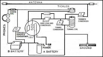 Using a variable "condenser" for a feedback throttle is still the best way to go. This diagram is the circuit configuration I think the Boy Electrician book should have presented. 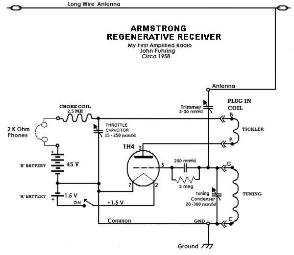 My Regenerative Radio today using modern electronic symbols. Doing a little research on how these radios were originally built in the 1920s, I discovered that nobody used a potentiometer to swamp out the tickler coil and the original way using a throttle capacitor was the best way to control the regeneration. Something that is part of the Scientific Method
Well, I think there's a good
lesson here and even at my age, it is good to experience such
things. I have crowed loudly about my superior way of
throttling
the tickler coil, but now I'm forced by experimental results to admit
that my method is not the best. The lesson here is just
this: if proof is offered that there is a better way to do something,
you must abandon your old ideas no matter how clever you originally
thought they were. Anything else is a
dishonest attempt to deceive yourself or others for the sake of foolish
pride. Just because something has been around for a long time,
that doesn't mean it is worth hanging on to if scientific evidence says
that there is something better.
Some
final words on my early radios
Well, that's the story of how I got interested in
radio and the story of the first radio I ever
made using an
amplifier. I am especially fond of this ugly little radio because
it's my earliest project that has survived to this
day.
I didn't invent the radio and yes, I got the plans out of a
book,
but still,
it
did contain some of my own ideas. Beyond all that, building
the
radio and getting it to work
taught me several important things regarding how signals flow through
circuits, how those circuits work and how vacuum tubes amplify.
It was this early specialization that lead to my career in electronics
and, although now retired, I still find enjoyment is this sort of thing.By the way, I have restored one of those really excellent Heathkit CR1 crystal radios. I have also designed a tiny crystal radio kit based on the Heathkit and have been having fun experimenting with crystal radios once again. The truth is, my Armstrong radio is far, far superior to either one of those crystal radios in terms of both selectivity and sensitivity. My recent experimenting has reminded me once again why the crystal detector, after it got the Radio Age started, was abandoned for Armstrong's designs. During that period after 1918 and until they were superseded by TRF and the early superheterodyne radios in the 1920s, radio enthusiasts knew that even a simple regenerative radio (like mine) is clearly superior to even the most elaborate crystal radio. The thing that held these early radios back was the really awful and terribly expensive early triode tubes that were the only things then available. Nevertheless, those early regenerative radios were so clearly superior to even the best crystal radios, that a lively market for those early triode tubes developed. Now that people could see how good tubes made better and better radios possible, a demand for better and better tubes developed too. This market drove the infant electronics industry so that by the mid 1920s, engineers and scientists had developed high-tech tubes sufficiently advanced to allow the development of almost all the modern circuits that are used today (using solid-state amplifiers, of course). Early
20th Century design, but using a crystalline triode
Today a regenerative radio based on Armstrong's
design can be made with a tiny and inexpensive transistor in place of
the triode tube. If
you
use a Field Effect Transistor (an FET), the circuit layout is almost
identical to the electron tube layout of the early radios. The FET
circuit shown below works on exactly
the same principle as the vacuum tube models except that
there is no need for an ' A ' battery and the 45 volt ' B ' battery is
lowered to just 9 volts. Instead of connecting the "grid
tickler" to
the
grid (pin 5), it would be connected to the 'gate' of the FET and the
'drain'
would
be connected as the anode (or plate - pin 3) and the 'source' would
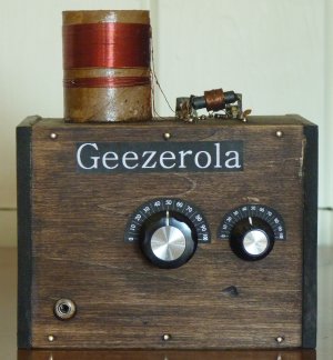
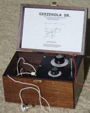
connect to the ground (or anode - pin 7). Other advantages of using a transistor as the regenerative detector are: 1) An FET is so much cheaper and easier to obtain than something like a 1H4 tube, 2) your one battery will last so much longer than the triode's 'A' battery, 3) the radio can be made smaller, 4) the radio is much more rugged and may even be dropped on the ground without ruining it, 5) there is no filament to ever burn out. If you are interested in building simple crystal radio or an Armstrong regenerative radio such as my Boy Electrician radio, I urge you to consider building the "Geezerola" radio shown below. It is so sensitive, you won't need an antenna more than a few feet long and it is so selective that you will be able to hear individual stations without them talking over each other -- even the ones that are close by on the dial. The radio is as simple, cheap and easy to build as the most basic crystal radios, but it out performs even the best and most elaborate crystal radios. A final question you must ask yourself
A question
remains though. Why would anybody today want to go to the
expense
and
labor to build
their own AM radio receiver? Yes, it would be as good a
learning
experience as it was when I was a kid, but today, in many areas of our country, the reward of
listening to something that would bring you joy is missing.
In many, perhaps most places here in the U.S. there
is today nothing a kid would want to listen to on AM radio or, in my opinion, nothing that would be
good for a young mind to hear.A Personal Lament On The Fate of AM Radio (You don't have to agree with) (Please skip to the end if you don't like biased opinions.)
I consider
myself very lucky to have been doing all that I did at a time just before AM
radio took its fatal plunge and started to degenerate into the "Hate
Talk Radio" that we have today. Back when I was having so
much
fun doing all this experimenting, AM radio still had on it things that
were well worth listening to and not poisonous to young minds as it too often is
today. Elvis, James Dean, Fats Domino and other popular music
stars were still on the AM dial as were all kinds of non-political news
and entertainment. I remember there was a single very hateful and
hate-filled "religious" radio station in town, but I avoided that part
of the dial. Today and for a long time now, there is in my broadcast area
absolutely
nothing on AM radio that I want to listen to or I would want a young
person, who has not developed his critical thinking yet, to hear.
Several years ago I wanted to make up a basic radio kit for my young nephew and see if he would find the same magic and fascination in electronics that I found when my aunt gave me a similar radio kit. I had been extremely impressed with my nephew when he was in elementary school and thought he'd be the perfect candidate for this sort of thing. I started to gather up the components for one of these radios and started listening to AM radio once again to see what was on. I listened to all the strong stations that a crystal radio could hear and I was sincerely shocked and disappointed at what I heard blasting all day long, every day. All that is left of my local AM radio (and AM radio in most places in the U.S.) now is this retched so-called "Christian" Fundamentalism and so-called "Conservative" hate talk partisan propaganda. Certainly nothing that is good or inspiring to help a young mind develop and certainly nothing a young person should listen to before he or she has achieved enough maturity whereby the difference between indoctrination and learning can be discerned. Yes, I was shocked at what I was hearing all over my local AM band so I scotched the idea of trying to get my nephew interested in radio the way I had. It probably wouldn't have worked anyway because, as my nephew transitioned out of elementary school, he soon dropped all interest in everything but motorcycle and truck racing. Still, I feel badly that AM radio has degenerated into what it is today and that I was never able at least try to introduce my nephew to that thing that I found so rewarding all my life. It is also sad for me to observe that, with the advance of digital technology and the Internet, it is probably just a matter of time before the Broadcast Band and Short Wave radio is altogether extinct and these wonderful old tube radios will become as quaint and useless as telegraph sounders. The warning I'm trying to give is just this: before you build or have a young person build any kind of AM radio, check your local broadcasting to see if there is anything good to listen to. If it is all political or religious haranguing, think about building something else. P.S. My nephew finally "found" himself and is now an apprentice electrician and absolutely loving it and all without the "help" of uncle John. THE
END
Having arrived this far,
obviously you have a superior attention span and reading ability that
far exceeds that of the
majority of web users. I highly value the opinion of people such as yourself, so I ask you to briefly tell me: Did
you enjoy this article
or were you disappointed?
If you have any detailed comments, questions, complaints or suggestions, I would be grateful if you would please E-mail me directly After 55 years, I have just built a radio based on the same design as this radio that you might be interested in  An Armstrong "Crystal" Radio from "The Old Geezer Electrician" Here's a easy to build radio of the exact design and performance, but nicer looking  The Geezerola Senior Regenerative Radio  My Regenerative Shortwave Radio. If you'd like to learn more about Armstrong's contributions to radio design, please take a look at my essay: 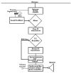 Basic Elements of Armstrong's Superheterodyne Radio If you are interested in how radio got started, perhaps you would like to read my essay on 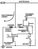 The Coherer and other early radio detectors If you are interested in learning more about the kind of radios that preceded the regenerative and later radios, I have a story about  A high performance Heathkit crystal radio I've completed a prototype crystal radio kit similar in design to the Heathkit CR1 that perhaps you would like to look at.  A simple but high performance crystal radio for advanced students and hobbyists. If you like reading about more complex homemade radios, perhaps you would like  My Magnum Opus ham radio story or you can  or, as a last resort, you can
Return to my Home Page and look for something else Notes * I have
recently come to the conclusion that De Forest's Audions behaved more
like thyratrons than triodes. I believe that the reason they work
so well as radio detectors is indeed because they have some gas in
them. It wasn't until many years later that scientists, who knew
much more about quantum physics, were able to explain that it was a
"avalanche effect" where a few electrons flowing from the hot cathode
and under the influence of the electric field of the grid could cause
the electrons of the gas molecules to be released in great quantities
and thus a small current in the tube would turn into a large current
very rapidly, thus amplifying the original small signal. It is a
fact that some tubes used by the British Navy had a special chamber
where additional gas could be added to the Audion if it started to
detect radio waves poorly.
With this in mind, perhaps it isn't so surprising that De Forest didn't understand his own tubes, but that doesn't explain the fact that he never seemed to understand how electrons moved in a high vacuum tube and how his and Armstrong's regenerative detectors worked. To me, De Forest is a real enigma. He made some solid contributions to the development of early radio technology, but for him to claim that he was the "Father of Radio" and then for him to later publish his silly rants regarding the "misuse" of his "child" (like broadcasting terrible stuff like Pop Music and advertisements) is just plane crazy and, for me, it shows what a fool the guy was. Please use your back button to return to the story. |