|
My 1938 Crosley "Super 8" model 817 Radio
A comprehensive story containing historical, educational, technical and biographical elements & opinions by John Fuhring Introduction
Before you begin reading this story, I want you to know that what is
presented here is more than simply an article. What I have written is a rather a long story
with certain autobiographical elements that I wrote for my own
entertainment. I am presenting this story to you free and
without commercials in the hope that you will be entertained by it too.
Please feel free to scroll down and skip around if you don't wish
to read the entire story.
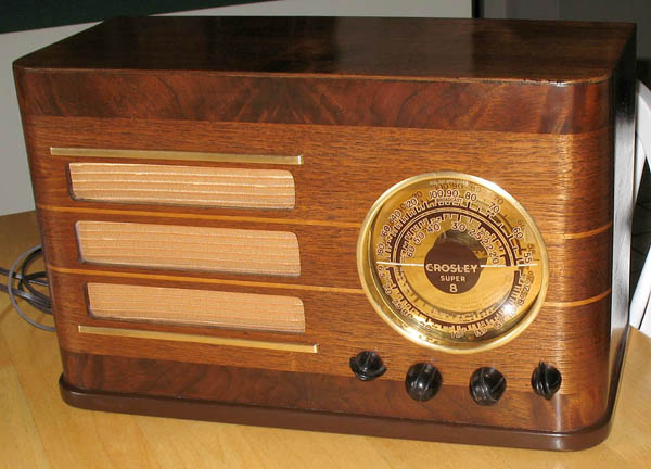 Here's a beautiful example of what a Crosley 817 is supposed to look like. Notice that the dial markings are on the glass dome and notice too that there is a shiny golden metal plate in the background under the dome giving it a 3-D look. A forgotten treasure from long ago
This,
as you may have gathered from the title, is a story of a 1938 Crosley
model 817 radio, but it is much more than a simple article about an old
radio, it is a story of the discovery of a long forgotten project
from my high school days and how I, five decades later, finally
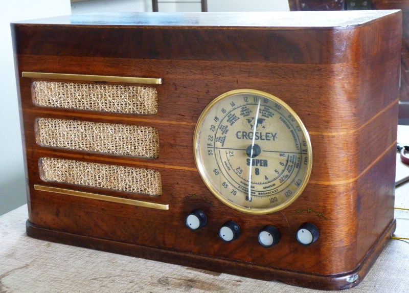
completed this project. Lately I've been cleaning out my old house and getting rid of decades and decades of accumulated stuff, mostly junk and not all of it mine. I just packaged up and sent my younger brother 150 pounds of his artwork and supplies dating all the way back to his high school days. As I worked my way into a storeroom in the back of my house, I was able to access storage shelves that hadn't been looked at in 50 or more years. Yes, I've been a pack-rat all my life, but now I'm doing something about it. As I was sorting out, rearranging, giving away and throwing out all this old stuff, way high up on a forgotten shelf I was startled to find an old radio. Laying on that shelf was a 1930s era radio, but I didn't immediately recognize it or remember how it got there. I took the old radio from its resting place and put it on my workbench for a closer look. The chassis was not bolted to the wooden cabinet, so I simply slid it out to get a good look at the chassis and its insides. The radio has several tuning coils and a bandswitch, so I knew that it was a shortwave model. I also noticed that it was a sophisticated radio with eight tubes and a large speaker. Underneath the chassis, some parts had obviously burned up and there was some sloppy workmanship in there. From a metal plate on the rear of the chassis I could see that the radio is a Crosley model 817. From the excellent old radio sites on the Internet, I learned that this model went into production exactly 75 years ago in July of 1937, but that it was considered a 1938 model. Just looking at it, the most obviously wrong thing about this radio was that it was missing its domed glass dial cover. Not only that, but the shiny golden metal plate that would have been covered by the glass had no markings on it. Obviously the dial markings must have been on the missing glass dome. I looked around, but could find no trace of the glass dome, not even fragments of it. As I looked at this radio, I racked my brain trying to remember where in the devil it came from. Gradually, throughout the day I began to recall events from my high school days and the little business I had fixing old radios. Somehow this radio must be related to that time. Slowly, bit by bit, I remembered that there had been a radio that I was unable to fix. To the best of my memory, this radio belonged to the family of a high school friend named a Bill P. (of whom I can find no trace on the Internet). I remember that Bill's radio was one of those "tough dogs" (an expression radio repairmen used in those days) because its problems were many and complicated and really beyond my skills at the time. I kept the radio on my workbench for a long time while I tried to get a schematic for it, but one day I accidentally broke the glass cover. I felt terrible because the dial markings were painted on the glass and without the markings, the radio was useless. I was ashamed to tell Bill that I had broken the glass, so I decided to try to buy the radio. Actually, I wanted to buy it to cover my embarrassment over breaking the glass dial. My friend wasn't too happy to sell me the radio, but he relented when I told him it couldn't be fixed and I wanted it for parts. I ended up offering and paying far more than what the radio was worth. What is more, I remember I suffered from a feeling of failure over this and it knocked a bit of confidence out of me. I fixed no more radios for people after this. I've (obviously) never been a person to throw anything out, so I must have put the hulk high up on a shelf in the storeroom where I knew it would be forgotten and lying there, out of sight and out of mind, it would not remind me of my failure. This exercise in "creative forgetfulness" worked all too well and so, when I came across the radio 50 years later, it took me a long time to piece together the history of this radio from fragments of old memories. The more I thought about it though, the more certain I became that this was the uncompleted repair job from over 50 years ago and with a wee bit of excitement, I realized that I now had an opportunity to go back in time and finish a job that had once caused me to feel disappointed with myself. It's hard to explain, but at this point in my life, I get a feeling of joy when I discover an unfinished task from my youth and an intense feeling of satisfaction when I finally bring that task to a successful conclusion. The longer the task has been delayed and the bigger the challenge it is to complete it, the more fun it is. When I complete one of these long delayed tasks, using skills and experience I didn't have in my younger days, I am so pleased with my little self that I want to show my work to my friends and (as silly and vain as this sounds) brag a little. This only goes so far because there are only a couple of people I know who will humor me in this regard. On the other hand, I want to "tell the world" about my project, so I write up the story and post it on my website and here you are, gentile reader from somewhere out there in the wide world, reading it. Clues revealing the repair history of this radio
As I opened up the radio and started looking
closely at its insides, I discovered that this radio had been worked on
many times and so it must have had an unusually long working life.
Obviously its former owners liked this radio so much, they kept
it going through several rounds of repair. To tell the truth, I
don't know exactly how many times the radio had been worked on, but
there were definite clues pointing to a few of those times. The
following guesses are based on the replacement parts I found inside the
radio and how the physical appearance of similar parts changed over
time. For example, I found a potentiometer with a "general
purpose shaft" indicating a replacement, but it was very large and old
fashioned and it must have dated from the early 1940s.It appears that somebody in the early 1960s (maybe it was me) had replaced the power cord. Earlier (probably in the mid 50s), somebody had added a newer technology filter capacitor. As mentioned, in the mid 1940s somebody had changed the volume control potentiometer. At or near this time, at least one coupling capacitor was replaced with a newer paper/wax (old technology) capacitor. Probably in the early 1940s, somebody replaced the two large filter capacitors mounted on the chassis with similar sized Olson general purpose capacitors and they slightly rearranged how certain components were placed in the chassis to accommodate those capacitors. At some point, the first detector tube was replaced with a new, Zenith brand tube and even now it appears rather new looking, indicating very little service. Unfortunately, due to a manufacturing defect, I later discovered that this tube's glass had cracked at the grid cap and, with loss of vacuum, it was dead. The two IF tubes, the second detector tube and the VFO tube all look well used and are of an old fashioned shape, so I believe they are originals. The audio output tubes together with the rectifier tube had obviously been replaced at least once with smaller, more "modern" "GT" types which is not surprising because these tubes operate under severe conditions of high current and voltage and get very hot in normal operation. The work that had been done in the mid 1950s was performed by somebody without a schematic and who obviously had a poor understanding of where to place filter capacitors. An electrolytic capacitor had been installed in such a way that it caused a power resistor to completely burn up, so initially I had no idea what kind of resistor it had been (2,000 ohm, 2 watt). I also noticed that the replacement parts were soldered in inexpertly. Of course, this could have been my work as I attempted to get the radio working back in the early 1960s, so perhaps I shouldn't be so critical. I have no doubt that this attempt at repair was unsuccessful and so I believe that it was at this time the radio stopped playing and had to wait for over 50 years to be put back in operation again. Rebuilding the old radio
As I wrote in the description of my Fairbanks Morse
radio, a good schematic is absolutely
invaluable if you
are to restore one of these radios. I will
not even start a project until after I have obtained and redrawn the
schematic for clarity and accuracy. That is exactly what I
did
for
this project too. I downloaded a schematic from the fantastic
source
of modern knowledge, the Internet , and then used the Paint program to
touch it up. The truth is, I generally spend more
time redrawing
and correcting schematics than I do actually working on radios.
If you have a Crosley 817 and you'd like a free copy of this diagram drop me a line.The importance of a good schematic diagram 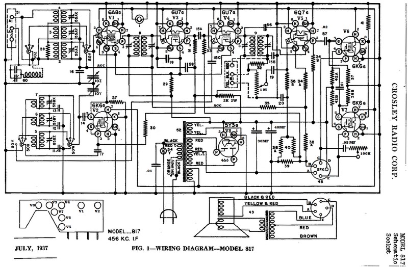
Rebuilding
the old radio
Of course, the first thing that one does after
taking
the chassis out of the cabinet is to turn it upside down and, with the
help of the schematic, a bright shop light and a strong magnifying
glass, trace all the circuits and identify all the parts I'd need.
When I looked at the underside of this radio, I was a little
dismayed to see that some of the components were so burned up that it
was
difficult to know exactly what they had been or just where replacements should
go, but the schematic would enable me to figure all that out. Installing new electronic parts and getting it to work Most of the capacitors in these old radios are made of paper, wax and tinfoil and there is no question that they and the electrolytic capacitors would have to be replaced. I started making up a list of the capacitors and other components I would need. It turned out that I only needed about a dozen ceramic caps and two electrolytic caps. I also needed two power resistors to replace the ones that had completely burned up. Armed with this list, I made a trip to my excellent Electronics Parts Supermart on a Tuesday morning (when they opened) and bought all the components for about $25. I needed to do some horse shoeing later that day, but when I finished doing both horses that afternoon, I was too sore and exhausted to do any work on the radio. Next day I put the parts in and the whole job took only a few of hours. Even though the job went quickly, I had to spent some time figuring out how to wire in the tiny little parts because the modern replacement components were not nearly long enough to span the cavernous distances inside the chassis. You see, the old parts were so large that they easily spanned the spaces between mounting terminations, but the small, new technology parts were just too small. As small as they are, the parts I used as replacements are all so much better and more reliable than the old parts, so they should last at least for the next 70 years and more. One of the burned up power resistors was a 2000 ohm, 2 watt unit that is part of a filtered high voltage supply. The other burned up resistor was a 375 ohm unit that self-biases the two audio output tubes. These output tubes work pretty hard, so I didn't want to use a smaller value resistor here because that would have lowered the bias and cause the tubes to draw more current. The closest thing to 375 ohms without going under 375 ohms was a 390 ohm resistor, so that's what I put in and it works perfectly with no "crossover" distortion. By the way, the grid cap connector that attaches to the 6A8 tube to the tuning condenser was missing and those things are hard to find these days, so I simply cut the neck off an old brass 7 MM Mauser cartridge and soldered a wire to it. It couldn't fit or work any better. There is one other thing that I always do before certifying that a radio is ready to turn on for the first time and that is to carefully remove each tube and burnish its pins with a fine wire brush. If the pins show any corrosion or contamination, I spray them with brake cleaner and wipe them off, then brush them until they are shiny. Applying power for the first time in over 50 years
Even though the radio didn't have a dial with
station marks on it yet, the dial mechanism worked and the tuning
condensers rotated, so I should have been able to tune in AM stations.
When I
was all done with the restoration work and after I had gone through
each circuit to make sure everything was wired according to the
schematic diagram, I began my sacred "Power Turn On Ritual" whereby I
solemnly and with great reverence, plug in the radio, bow to the
Spirit of Radio, take a deep breath of the "Luminiferous Ether"
that surrounds the whole universe and then with heart-stopping
anticipation, I turn on the power switch. I watched the tubes light up and
listened for white noise to emanate from the speaker. Well,
the tubes lit up, but I could hear very little white noise from the speaker because this radio's
audio
amplifier and filtering is so good. With a growing sense of anxiety, I then set the band switch to the AM
broadcast band and tuned back and forth for a station.Oh no!! Nothing. The radio remained silent. My "Power Turn On Ritual" had not worked this time and nothing came out of the speaker. Feeling quite disappointed, I realized that there was something major wrong with one of the many components or I had made a mistake. A mistake?? Me make a mistake?!? Me, the world famous "Doctor Frankenstein" of electronics who is so justly famous for jolting old dead radios back to life with charges of high voltage electricity, ME -- MAKE A MISTAKE!?! Such a thing is unheard of, so some part or other must be burned out. I only hoped that it wasn't something major like the power transformer. Troubleshooting and getting the radio to play
Well, when a radio isn't working the first
thing
one does is take the schematic and a digital volt meter and go around
and check all the positive and negative voltages. There are several positive high voltage points
ranging from around 250 to 120 volts DC, but they all checked out good.
There are several negative voltages ranging from 100 to 3 volts
DC, but they all looked good too. So, the problem wasn't with
the power supply (I was glad to learn). While I was doing this probing, I noticed that
I'd introduce loud hums when I'd probe places that normally produce
loud
hums (like the grid of the second detector tube) and in that way I knew
the audio stages were working and that was good.Next I got out my little signal generator and set it for 455 KHz, but before I could even hook it up, I could hear the generator's modulated output in the speaker. I knew the IF amplifiers, the detector and audio stages were all working. Next I connected my frequency counter to the local oscillator tube and saw that it was putting out a signal on the correct frequency. So far I had determined that the local oscillator, the IF, the 2nd detector and all the audio stages were working. I tuned my signal generator to 455 KHz above the local oscillator's frequency and heard nothing. Well, that meant that the failure was in the first detector stage, so I measured all the voltages around the 6A8 tube and found that they were exactly right. Screen, anode, cathode, grid bias, everything was just fine, so the tube itself must be bad, but this was a "new" looking tube. I removed the tube and when I looked closely at it, I could see that it had tiny cracks near the grid cap and air now filled the tube. With the vacuum gone, this wonderful old tube was dead and even I could not bring it back to life. Fortunately, my Fairbanks Morse has the same first detector tube (a 6A8) so I swapped the two tubes and within seconds, the Crosley came to life and started receiving signals. I then got on the Internet and ordered a new 6A8 from my favorite supplier in Florida. Two days later -- TWO DAYS later folks, the US Post office had the new tube in my hand and I had payed nothing extra for such rapid shipping. For those who think that Government can't do anything right, I suggest that your belief is based on ideology bordering on some kind of goofy fundamentalism and certainly not based on reality. If I would have had the tube seller ship my tube by any commercial carrier, it would have taken a couple of weeks and would have cost a lot more money -- I know by experience. By the way, I suspected that the very ancient local oscillator tube might be weak so I ordered a 6K6 at the same time I ordered the 6A8 and I'm glad I did. You see, after the radio had been in operation for a few days, I noticed that it would go dead when I'd tune to certain portions of the upper shortwave band. On checking the "grid leak bias" of this tube, I noticed that it was incredibly low (-3 volts) and the tube was barely functioning. Sadly, I removed the ancient tube with its bulbous "G" shape and replaced it with a "modern" tube with a slimmer "GT" shape. On replacement, the "self bias" voltage on the grid went to -27 volts, and the upper shortwave band has really come alive. Well, after 75 years of hard work, perhaps it was about time the local oscillator tube was retired. Substituting for the missing dial
Back 50 years ago, when I broke the original glass
dial, that put an
end to my attempts to fix the radio. Not having a dial is
what
prompted me to put the radio on its
shelf in the first place. Even now I have to either put the radio back on the shelf or have to
throw it away if I couldn't buy a dial or somehow make a useable one myself.
Let's face it, without a dial, this radio is just a silly
looking piece of junk and certainly not something you'd want to show people, even if it worked.
To
bring it back to some kind of usefulness, it was of prime importance to
somehow get or make a dial for this radio. Buying a dial was out of the question, so somehow I had to make one.My first attempt at making a dial was to try to melt a Plexiglass disk into a dome shape and then, if that worked, stick transparent lettering to the inside of it. I sure wasted a lot of time and ruined a perfectly good piece of Plexiglass, so I abandoned that idea. After giving it some thought, I came up with another idea. 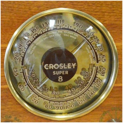 The original dial with markings printed on the glass dome. Reading what collectors say about this model, it appears that a broken glass dial was a common occurrence and many otherwise good radios were scrapped because of a broken glass dial. I'll bet that replacement glass dials were a hot selling item for this model back in the late 30s and 40s. I wonder if their might be a whole stack of them sitting forgotten on some cluttered shelf in a warehouse somewhere. Not long ago I bought a WW2 era Hallicrafters EC-1 radio who's dial was in horrible condition. I used my computer to help me draw and print a new dial and, if I say so myself, it looks every bit as good as the original dial. 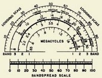 My reproduced EC-1 radio dial If I could make a dial for my EC-1, I figured that I could do it for my Crolsley. I began to search the Internet for images of a usable dial and I found one. I downloaded the image and then, with my computer's Paint program, I modified it for use with my Crosley. My first attempt at making a usable dial
 At first I was very pleased with this dial and it did bring the old radio back to some kind of usefulness. Eventually it had to go. They were so tiny, I just couldn't read the numbers. I used that dial, but became more and more dissatisfied with it because the numbers were so small. I then found a really beautiful dial that had the big numbers that I wanted so that they would be much easier to read. This new dial tuned clockwise, but my Crosley tunes counter clockwise. Most old radios tune clockwise, but about 20% of them tune counter clockwise like my Crosley. Now I must tell you that making a usable dial from the image I downloaded was not all that easy. First of all, the dial was multicolored and very, very flashy and it was made to be illuminated from the rear. For my radio, to match the overall design, my replacement dial must have dark numerals on a white background. To achieve this, I turned the image into a "negative" and then I turned the whole thing into a gray scale image. 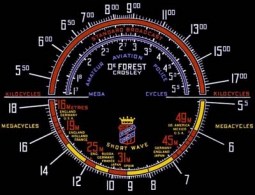 This pretty dial for a De Forest Crosley was too colorful. I turned it into a negative image and then a gray scale image. My initial dial requiring a lot more work: 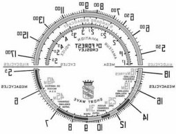 To make matters difficult, my radio tunes backwards, so I had to reverse the image and then reverse each word and number. I also had to move the numbers in so it would fit inside the round dial plate. It was a bit of a chore, but here is what I finally ended up with: 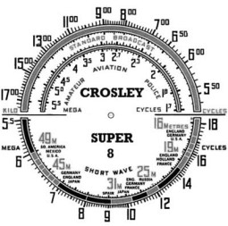 I printed this dial out and gave the paper a "light oak" wash to match the overall look of the wooden cabinet. When I installed this dial in my radio, I loved the way it looked, but it had a fatal flaw. An Inconvenient Truth I
had to face an "inconvenient truth" and that
"truth" was that my great looking dial -- the dial that I was so
proud of --
just wasn't working out. The dial numbers just didn't match
the tuning range that my radio's circuits were
designed for. The Broadcast Band was OK, but my short wave bands
were designed to tune from 2.1 to 22 megahertz and not the 1.7 to 18
megahertz range of this dial. No matter how I adjusted my
radio's tuning, I just couldn't get it to match the numbers on the
dial and there was no way I was going to rewind the tuning coils.
Since I couldn't live with a radio who's dial didn't match
its actual tuning, no matter how "pretty" it was, I had to find another
dial.
Well, I finally found a dial with the proper tuning range, but one not as pretty and certainly not nearly as easy to modify for the reverse tuning that my set requires. 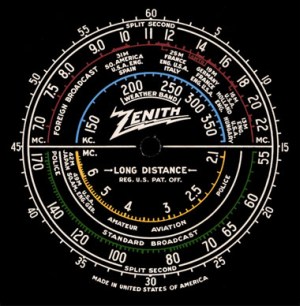 This dial had a long wave band and a lot of other superfluous markings that had to be removed. 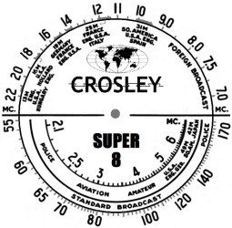 Here's my dial after turning it into a negative, cleaning off all the superfluous markings and after reversing everything. I really regretted how plain it looked, so to "jazz it up" a bit, I added a tiny world map. The paper dial was given a "light oak" wash with a staining varnish to protect the markings and match the wood of the cabinet. If you are restoring this or a similar model radio with a shattered or missing dial and you would like a high resolution copy of my dial, drop me a line. Believe me, this dial was much, much harder to reverse than the other one. I worked on it for about 12 hours using two different image programs, swapping images back and forth, to get the effect I wanted. Yes, it was a lot of work, but I now have a dial that not only looks good, it's easy to read and the tuning is correct. After 50 and more years, I think I finally have a replacement dial for my Crosley that allows me to show off the old radio and be proud of how it looks. An original dial and my ersatz dial
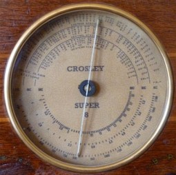
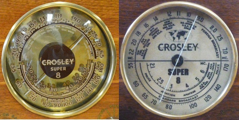 Here is an original dial and my homemade dial side by side. Actually, they both look better in real life than these photos show. The tuning range of the new dial is so close to the original that it was a simple matter to "tweak" the oscillator and antenna tuning circuits to match the dial markings. Without an original glass dome with the original markings, my radio can not be considered restored to original condition, but I think it is quite good enough and I am proud to show it off. I think that my new dial looks as good as just about any other period radio and better than some, but what is more, it exactly matches the frequencies of the on-the-air stations when you tune to them. The WWV stations are just where the dial says they should be and so is everybody else, so I couldn't be more pleased in that respect. I finally have a dial that is not only easy to read, but exactly matches the original tuning ranges of the radio's two shortwave bands. It is right on the money as if the dial had been originally designed for this radio. By the way, it so happens that my Fairbanks Morse's two shortwave bands have almost the exact tuning ranges too. You might ask, why it is so important to me that my dial indicates correctly: well, I listened to shortwave the night after I had the new dial in. English language stations were coming in strongly and somehow it was a lot more fun listening to shortwave and knowing that my dial was accurately telling me what frequency I was on. I know it is foolish, but I was very much bothered when I knew that a station's frequency and my dial didn't match and it took a lot of the fun out of tuning around the short wave bands. Crazy, no? Oh yeah, there's something else I discovered; my Fairbanks is noticeably easier to tune way up in the higher frequencies because the Crosley has a higher "gear ratio" and is a bit more touchy. Actually, for tuning AM stations, it doesn't make a whole lot of difference. Making a Plexiglass dial cover
The original dial
markings of my Crosley had been printed directly on the glass dome with
a shiny gold
plate in the background. That glass performed two functions,
first it was the dial and second it formed the glass cover over the
opening in the cabinet. After I had a dial with markings printed
and installed on the rear plate, I very, very carefully cut
out a flat Plexiglass disk for the dial cover. The hardest and most exacting part of this whole restoration project was cutting out the Plexiglass window and then making it round. I made a test plate that didn't turn out to be useful, but by working on this test disk, I learned how to cut and form Plexiglass. On the second attempt and by being extremely careful, I was able to successfully cut out a disk of Plexiglass just a little larger than what I'd need. By a tedious, careful and slow process of grinding the edge of the Plexiglass disk by hand, I was able to get it into a nearly perfect circle that exactly fits within the brass escutcheon ring, as you can see. If I say so myself, I did a very nice, you might even say, professional job. The Plexiglass disk fits perfectly, it looks very "factory made" and gives the radio an overall handsome look (in my opinion). Perhaps I'm a bit prejudiced, but I think my radio's homemade dial looks as nice as the dials of most of the other radios of this era, maybe even better than some. At any rate, it sure beats scrapping this fine old radio just because I broke the glass dial 50 years ago. Troubleshooting and replacing a failed component
A couple of days after I had the radio working, I
turned it on and had it on all day long. With the radio playing
in the background, I listened to programming rebroadcast by my
little AM transmitter. At first the radio sounded just great and
I noticed nothing wrong, but after the radio had been on for 3 or 4
hours, I noticed a slight crackling sound that I thought might be due
to my little homemade AM transmitter. I fooled with the
transmitter, but couldn't make the crackling go away. I then
tuned to a weak station and there was no crackling so I again assumed
it was with my little transmitter. After a while it dawned on me
it might have something to do with the bias on the IF tubes so I tuned
to a strong station and there was that familiar crackling again.
Hummm, obviously the problem was NOT with my transmitter, but was
in the radio itself. and how my prejudices and assumptions were wrong A few days earlier I had helped a guy troubleshoot crackling in his radio and so I zeroed in on a coupling capacitor in the second IF amplifier stage. When I put the probe of my digital voltmeter on the grid of the second IF amplifier tube, I expected to see around minus three volts of bias, but the voltage was all over the place and even showed a positive bias. A positive voltage?!? Something was either wrong with the coupling capacitor or the tube was shorted internally. Since the coupling capacitor was an original silver mica cap and since I had never had a silver mica cap go bad, I initially dismissed the cap and suspected the tube. I removed the grid cap, then I pulled the tube out of the radio while the set was still on. I expected the bias to go way down to minus three volts, but when I checked it with my voltmeter, it did no such thing. It wasn't the tube, it was the silver mica capacitor. Oh no, could I possibly be wrong about silver mica caps never going bad?? Yes, here was proof positive that I was wrong -- again -- at least in this instance. The cap was a 100 PF unit and it so happened that I had a ceramic cap that measured exactly 100 PF, so I changed capacitors. When I turned the radio back on, the grid bias immediately measured the correct negative 3 volts and when I plugged in the IF tube, the bias remained at negative 3 volts. What is more, the audio sounded pure and without any crackling. I left the radio on all evening and confirmed that changing the cap fixed both the the crackling and the grid bias problem. Technical differences between my Crosley and my Fairbanks Morse.
If you are
interested in learning about mid to late 1930's
consumer radio technology, I have written up a description of my
Fairbanks Morse radio's inner workings that I can recommend to you.
I think the Fairbanks radio is the appropriate radio for this
discussion because it is a
relatively simple radio that takes advantages of the enhanced features
that the recently developed tubes of that era offered to radio
designers and its overall design is what most other manufacturers built
their radios to. My Crosley, on the other hand, is a more complex
radio
designed as a more sophisticated radio with better sound. My
Crosley's manufacturers wanted to market this radio to a more affluent
and upscale buyer who actually wanted more tubes in their radio so as
to get a little bit better sound. In the paragraphs to follow, I
will briefly describe only those radio circuits that are different from
the Fairbanks Morse while assuming that the Fairbanks is a standard by
which this radio is judged. In most respects, the Crosley will be
the superior radio, but the truth is, if I was living in that era and
was in the market
to buy a radio, I'm pretty sure that I would have chosen the Fairbanks.
To save on manufacturing cost, the price of an expensive tube, a slightly smaller (and cheaper) transformer and to make the radio chassis more compact, most mid-1930s manufacturers designed their radios to take advantage of the "new" pentagrid converter tubes that could combine both the local oscillator and the mixer into one tube. The 6A8 first detector tube in both my Fairbanks and the Crosley is a good early example of this kind of tube, but, for some reason, the Crosley designers decided to use a separate local oscillator tube. I really have no idea why they did that except perhaps they thought the radio would have slightly better performance at the higher shortwave frequencies and it's true that the local oscillator is slightly "pulled" by the tuning of the antenna stage when both the local oscillator and mixer are combined in one tube. To me, this is just a waste of a tube, but it does increase the tube count and we all know that the more tubes you have, the more prestigious is the radio. Besides, with high status cars all having V-8 engines, having a "Super 7" radio isn't nearly as cool sounding as having a "Super 8" radio. Obviously the Fairbanks Morse was for the Ford buyer whereas the Crosley was for the Mercury buyer. Here's another strange difference. With good high gain, variable transconductance pentode tubes like the 6K7 or the 6U7, most radio designers found that a single tube in the IF stage is quite good enough. For some reason, the designer of my Crosley decided that if one tube was good, two would be even better. My guess is that this extra IF tube is in there to give the radio slightly better drive for their somewhat unconventional automatic volume control circuit, reduce the chances of the IF strip going into self-oscillation and a way of lowering the IF amplification (gain) when operating on the AM band and have higher gain on shortwave. Of course, with the "modern" pentode tube they were using, self-oscillation wan not a problem and those other factors are trivial, so I still can't figure out why that extra tube is in there except to increase the tube count for prestige purposes. As I briefly mentioned, my Crosley generates the automatic volume control (AVC) signal slightly differently from the standard Hazeltine AVC process. The negative DC for the AVC is not generated by the audio detection diode, but has its own carrier detection diode that that is fed its signal from a circuit that precedes the last IF filter transformer. This would give the AGC a "broader" response so that nearby stations would also effect the AVC. I can't see much advantage in this, but it might slightly reduce the interference caused by nearby stations. Maybe. At least, this is what I think it would do. To tell the truth, I don't know why they did it this way and it sure isn't the way I'd do it or the way other radios designers have ever done it. The only other thing I can think of is that Crosley was somehow trying to get around Hazeltine's AVC patents. Finally, this radio has what is called a "push-pull" audio output stage. The technical term for this is a "Class AB2 amplifier" and for all you music lovers, this configuration is the most linear, has the lowest distortion and the best frequency response of any other class of audio amplifier. It is also the configuration that allows the output tubes to put out maximum power and this extra power is then available to run the radio's big, high fidelity, low efficiency speaker. Speaking of speakers, the Crosley's speaker is considerably bigger than the Fairbank's speaker and noticeably sounds better. Of course, these were AM radios and AM is notorious for poor sound quality, but a person with a good ear and listening to a strong local station broadcasting good, low distortion high fidelity music, this extra sound quality would make all the difference in the world and this would be the radio (s)he would want to own. Personally, with my "tin ear" and my hearing loss in the upper frequency ranges, I doubted that I could tell the difference between the way my Fairbanks sounds and how much better my Crosley would sound. So, what are the other major differences between my Fairbanks Morse and my Crosley. First, they are both housed in attractive wooden cabinets of similar size. It is, no doubt, very pretentious of me to say this, but to me the Crosley looks somewhat more "modern" with a simple, but sophisticated Art Deco look that has very clean lines whereas the Fairbanks is more a "Baroque" or "Victorian" kind of Art Deco that is a little closer to the older "Art Nouveau" from which Art Deco evolved. The Crosley's more "modern" (original) dial isn't nearly as colorful as the Fairbanks beautiful dial, but I'm sure many people liked it that way. The Crosley has a slightly higher upper shortwave frequency limit, but otherwise they are almost identical in their band coverages. The Crosley has eight tubes and the Fairbanks has "only" five tubes and is therefore less prestigious -- I guess. Finally, the Crosley sold at a higher price and with the extra tubes and more complex circuits, it would have been a slightly more expensive radio to keep working. I did notice that it used very high quality capacitors and resistors and so the Crosley would have been quite reliable. However, when it needing fixing, it it would have cost more to repair than the Fairbanks because the technician would have had to spend more time on it. 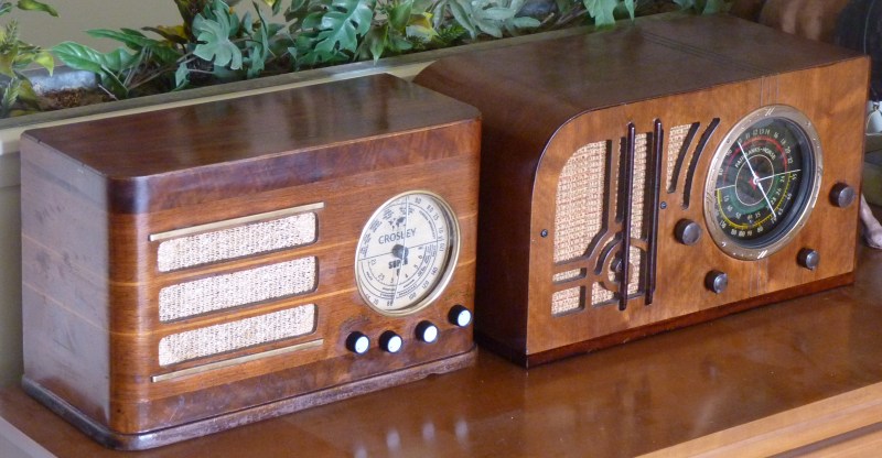 My two 1930s radios side by side They are nearly identical in height and width, but obviously the Crosley is thinner. I think the Fairbanks Morse is a more handsome radio with its big colorful dial, its excellent knob placement and more ornate cabinet, but the Crosley has three more tubes, a better audio output stage, a continuous tone control and its speaker is much larger. They both have three bands and have similar shortwave tuning ranges. OK, since writing the above I've had an opportunity to play both radios side by side and carefully compare how they sound. I tuned both to a strong local Mexican station that plays polka music (with a Mexican twist). As with all German old style music, it has lots of low frequency oompah, oompah sounds along with drums, trumpets and violins. I really hate to admit it, but the Crosley's sound was noticeably superior especially with regard to bass. The Fairbanks Morse did well in the high ranges where it might have had a slight edge and it did well at midrange, but altogether, the Crosley sounded best and its continuous tone control was also superior. On voice only, the two radios were pretty similar. With regard to sensitivity, they both seemed about the same with perhaps the Crosley being slightly better at pulling out very weak and noisy signals. I have hearing loss and I am a poor judge of good audio, nevertheless even I can easily tell the difference between the two radios. Where the Crosley really shines is its superior audio output stage driving a large speaker with a continuously adjustable tone control. The Fairbanks' audio stage consists of only one tube driving a small speaker with only a "bass" and a "treble" tone control setting. Personally, two settings is good enough for me, but I'm sure there are a lot of people who would appreciate the better tone control. Deciding which radio to buy for your home in 1938
A family's home decor might have had an influence on which
radio to buy. Those with a "modern" home and "streamlined"
Art Deco furniture would probably like the Crosley whereas the
Fairbanks Morse might look better in a more elaborately decorated "Art
Nouveau" home.
What do you think? Aside from the styling of the cabinets, the only real difference between the two radios is the sound. As mentioned, the Crosley's audio is clearly superior and that would have been the deal-maker for many people, but the beauty of the Fairbanks Morse's cabinet, its lovely and colorful dial, its lower price and its very adequate sound quality would have been the deal-maker for me. How about you? Clean, modern styling and superior sound = Crosley Beautiful dial & cabinet & with good sound = Fairbanks Morse I'm sure that buying one of these beauties for the price they sold at wasn't a light decision and a lot of factors were weighed before deciding which one to bring home. Future improvements
To extend the usefulness of my Fairbanks Morse, I
installed a very nice and very stable BFO. This BFO allows me to
tune in Morse code and single side band ham radio transmissions and I
plan to install one of this radio too. The problem within the
Crosley is that the tone control isn't a rotary switch, but is a
potentiometer therefore I am going to have to rig up a unobtrusive
on/off switch to control this BFO. I'm in no big hurry to do
this, but plan to do so soon.
The following BFO section was taken from my Fairbanks Morse story 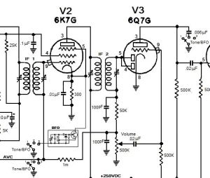 Diagram showing the placement of a little FET BFO module and the three ganged Tone/BFO Control switchs. The first two positions control the tone, the third position turns on the BFO. 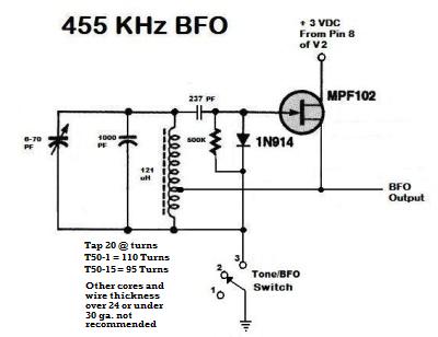
The shortwave bands are only a
shadow of
what they once were, but with a BFO such as this, much more listening is suddenly made available. If you
have
one of these wonderful
old radios, you might consider adding one of these circuits too.
Nobody will ever know you have put a BFO in there just by
looking
and the radio
will work and sound exactly the same on AM, but by having one, you will
have a more useful radio. Of course, listening to most hams
talk is about as much fun as watching paint dry, so you will have to
decide if adding a little BFO is really your "cup of tea" or not.
If you do decide you want to add a BFO to your old radio and you
need some advice, drop
me a line and maybe I can help.
The
life and times of Depression
Era radios
(most of this essay is taken from my Fairbanks Morse story) I should mention though that these radios were all hand wired and by today's standards, extremely expensive. My Crosley sold for about $45 or the equivalent of about $800 to $1,000 in today's money. These were a major purchase (next to a house and car) and so most people had only one (and room for only one) radio back then. Having a radio that sounded so nice and could tune in the whole world, must have been a great source of pride, in addition to its obvious entertainment value. I can only imagine how excited, pleased and proud the person was when he or she first took this radio to their home and plugged it in for the first time. I'll bet they invited the whole neighborhood in to listen to it while everybody remarked at how it sounded every bit as good as a set twice its size. The voice of President Roosevelt must have sounded many, many times in the very speaker I'm listening to and the electrical undulations of his voice must have modulated the electron stream of many of the very tubes that are still in this radio as he gave his comforting and intimate "Fireside Chats." I can just imagine the whole family sitting around such a radio at night listening to this or an exciting drama, a comedy show or a news broadcast of some important event - like a King's Speech or the attack on Pearl Harbor or the Invasion of Normandy - while during the day the radio would fill the house with the latest big band and jazz music or a baseball game on a lazy Saturday afternoon in summer. Between shows everybody would be informed regarding the advantages of Palmolive Soap (made with palm and real olive oil), the pleasures of chewing Wrigley's Gum, how people's lives are ruined forever by not using Listerine to combat their bad breath, the efficaciousness of Doctor Vornoff's Monkey Gland Treatment, how if you drink Ovaltine before going to bed, it will help you sleep and you will wake up GAY in the morning (which today not everybody thinks is always a good thing) and how more doctors smoke Camel cigarettes than any other brand (my dad was a doctor and that's what he smoked, of course, he died young). It somewhat boggles my mind to think of the wonderful programming and the dramatic events of world history this radio must have tuned into during its working life. It gives me an indescribable feeling to realize that the great entertainers and the news of the important events of the Second World War were listened to using this radio. I love these old radios for their beauty, their interesting technology and the fact that they are an important and key artifact of our culture and civilization from a very important time in the history of the world and my country. I don't know what model radio my parents and grand parents owned during this period back in the 1930s, but whatever they owned, it was something very similar. Conclusion and some additional thoughts after restoring the radio
My radio had to
wait 50 years before it was made ready to play once again and, you
know, that's a long time for something to finally get fixed.
Of course I have plenty of excuses for being so tardy.
First and foremost, only the development of the Internet made
this restoration possible and I have to admit that back in 1960 I just
didn't have the tools or the smarts to do this
job. Armed with a good schematic, excellent quality replacement
parts AND the training and experience that took me this long to
develop, finally, after all these
decades, it was now possible to bring this radio back to life.
This radio began life in late 1937 and was used until at least the mid 1950s. It thus provided entertainment for over 15 years. Judging from how the users of this radio had worn out the volume control and the audio output tubes and how often it had been repaired, this radio must have provided a lot of entertainment during its first lifetime. Although the old radio has been made ready for its second life, it is highly unlikely that it will ever be used as extensively as it formerly had been and we all know why. We all know that there is hardly anything left of the once wonderful AM band worth listening to. Because the broadcast range of an AM station is so limited, because a huge amount of expensive electricity is necessary to get an AM signal out, because noise easily creeps in on a signal and because the audio quality is inferior to FM, the AM band has been abandoned to the bottom feeders of right-wing propaganda and religious Fundamentalism and their hateful programming. Programming that rots people's brains by telling them what they want to hear, not what they need to hear. Programming featuring mean spirited "hosts" who's vile, increasingly vituperous speech has, in fact, made the whole country mean and divided. By the way, these last few nights I've tuned in KGO in San Francisco (about 200 miles away). To my great sadness, this once wonderful old station has gone to an "all news" format and has dropped all local programming. Thus the last decent thing to listen to on AM radio has died. KGO radio was one of the very first radio stations. It started life in 1924 but by this year, 2012, it has joined the dead or soon to be dead leaving the AM broadcast band completely empty of any quality programming worth listening to. It makes me so very sad that this has happened, but all things must die in the end and for each of us the once sanguine world of our youth must turn gray. Thus it is for the individual as well as institutions. Even nations and some day the human race too must become extinct. Let us enjoy what can be enjoyed while it is still possible and remember that the most precious things are thus precious because of their mortal nature and the pleasure they bring is all too ephemeral. "Man, born of woman hath but a short time to live." "Like a flower he cometh up and is cut down." "He fleeth from place to place as it were a shadow and never abideth in one stay." Not long ago, recognizing how barren the AM broadcast band had become, but wishing for something good to play through my old radios, I built a low power AM transmitter and I am so pleased that I did. If you have one of these wonderful old radios and it has been restored to working order, you very well might want to either build or buy an AM transmitter because, in the words of the old saying that I made up, "if you want something done at all, you have to do it yourself" and that applies to broadcasting for yourself something decent to listen to. Good luck and have fun with your old radio. THE END
Having arrived this far,
obviously you have a superior attention span and reading ability that
far exceeds that of the
majority of web users. I highly value the opinion of people such as yourself, so I ask you to briefly tell me: Did
you enjoy this article
or were you disappointed?
If you have any detailed comments, questions, complaints or suggestions, I would be grateful if you would please
E-mail me directly
If you have an antique AM radio and you need something decent to listen
to, perhaps you should buy or build your own
 Low Power AM transmitter I have restored a beautiful shortwave radio from this era that you might be interested to read about 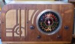 My beautiful Fairbanks Morse radio If you liked this story, you would probably like my 1936 Troy Radio story 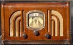 Please
go to my Troy Radio Story
For a simplified, but more in depth explanation of how this and similar radios work, you might be interested in 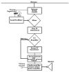 An essay on the Armstrong Superheterodyne Radio Principle I
have a lot of other old radio stories and radio related essays on my website
 For
other stories and things,
|