|
My
"King's Speech, Fireside Chat" Radio
A comprehensive story containing historical, educational, technical and biographical elements & opinions by John Fuhring Introduction
Before you begin reading this story, I want you to know that what is
presented here is more than simply an article, but rather a long story
with certain autobiographical elements that I wrote for my own
entertainment. I am presenting this story to you free and
without commercials in the hope that you will be entertained by it.
Please feel free to scroll down and skip around if you don't wish
to read the entire story. The following several paragraphs are
autobiographical, but I do not wish to impose my biography on you if
you think it would be very boring, so you may skip
ahead to the technology section if you wish to.
How
and why I got my Fairbanks Morse
By high
school, I was already a hopeless nerd. By then I had learned to love
old
radios and love fixing them up to make them work again. For a
while, I even had a little business going fixing up old radios for
friends of mine. I had amassed a collection of wiring
diagrams of
many "modern" miniature tubes that I could
substitute for the large old fashioned tubes in the old radios.
Because the layout of old radios are generally so simple, I
could
do basic
troubleshooting,
put in new tubes and replace capacitors without
schematic diagrams. It was a lot of fun and although it
(obviously) had
a deleterious effect on my social development, it did contribute to my
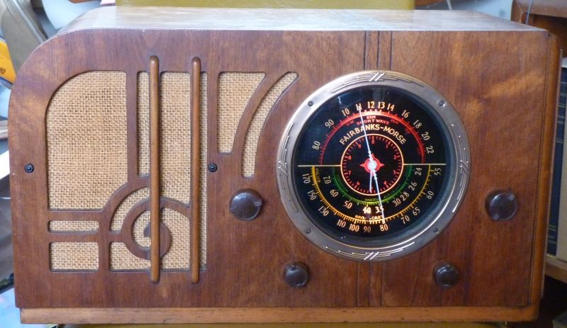
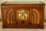
later career in electronics.After working on a few of these wonderful old radios for my friends, I wanted one of my own, so I started looking around and asked my parents to look around too. My folks found for me a 1936 Troy Radio (a beautiful radio I have recently rebuilt) and a friend of mom's dropped off a 1942 Philco portable radio I have written about elsewhere on this site. Neither of these radios was what I really wanted because they covered only the AM band and I wanted an old radio with shortwave. The Troy Radio was made bedroom or small apartment radio and the Philco was made after shortwave listening had lost most of its popularity. Of course, there was no eBay back then so I had to wait until an opportunity arrived by chance whereby I could pick up an old radio with shortwave. Some time around 1960 I found a beautiful "Cathedral" style Philco "Baby Grand" radio in a back alley trash pick up and it had a shortwave band. I quickly dropped off my bicycle and then returned for the radio before the trash truck showed up. I took the radio home, cleaned it up and within a few days, had it working again. Doing some recent research based on my memory of the radio, I believe it was a 1934 model 18 with 8 tubes and a powerful "push-pull" audio stage. I remember that the sound coming out of its big electromagnet speaker was beautiful and it could really pull in shortwave stations loud and clear with just a short antenna wire. I also remember that it was limited to one low frequency shortwave band and it too turned out kind of useless. I loved that radio, but when I returned from military service in 1969, I discovered that a lot of my old stuff was gone. My parents claimed that they had taken my stuff out to the garage for storage and that it had probably been stolen from there. I was extremely skeptical of that claim and I always suspected that they had simply given or thrown away stuff they considered old junk. Well, there was no help for it, my Philco Baby Grand was gone forever. Sure, I felt bad about it and I was angry with my parents for letting it be stolen (or more likely - given away), but by then I had moved on with my interests and I wouldn't rediscover the joys of old radios until several decades later after I had retired. A year ago an old friend showed me a couple of old radios of his after I expressed an interest in them. After seeing them, I told him I could get them working again if he'd let me. I took them home, downloaded schematics off the Internet and that's when I rediscovered how much fun working on these old things is. Subsequently, I have fixed or put back together several old radios and stories regarding those projects are located elsewhere on my web site. Fixing up all these radios got me longing for my old Baby Grand again, but this time I wanted a slightly better radio with better short wave coverage. First place I looked was eBay (where else?) and I found what I was looking for. I put in a few bids on some interesting radios, but most of them went for too much money so I'd usually drop out of the bidding. I did make an excellent deal on a Hallicrafters EC-1 sold for junk and parts only. Finally a Fairbanks Morse model 58 with a really beautiful dial, built during the right era (1936) and having exactly the shortwave coverage I wanted came up for bid. It too went for way too much money so I let it pass, but then a few weeks later I was notified that this same radio was up for bid again. Well, the second time it went up for bid, the price did not reach such an insane level and although I really didn't want to pay as much as I did, I bid enough to win the auction. Now that I have the radio and now it is working so beautifully, I don't grudge the amount I paid. The seller was real good about sending it and it arrived from Tennessee ahead of schedule thanks to the efficiency of the US Postal Service. It was there on my porch waiting for me when I arrived home on a Friday afternoon well wrapped and in good condition. When I unpacked it, I was pleased that the wooden cabinet looked good, but not at all surprised that the electronics in the chassis had obviously not been touched in 50 years except to replace a power cord. I wasn't at all disappointed to find that the tuning mechanism was frozen and needed remounting on new rubber pads and that all the paper and electrolytic capacitors were in a horrible state, because I expected a radio this old would be this way. So, I finally had one, a 1930s era radio with good shortwave coverage. It is hard to explain, but not having one of these radios was something I had left undone for five decades and now, all of a sudden, it became a big part of my fun to finally complete a project that had been neglected so long. Wouldn't it be great if all those other things in life that were never completed or done badly could be likewise revisited and brought to such a satisfying conclusion? Such is not in the natural order of things and I have to be satisfied with small triumphs. How
my Fairbanks Morse works.
A good schematic is absolutely
invaluable if you
are to restore one of these radios. I will
not even start a project until after I have obtained and redrawn the
schematic for clarity and accuracy. That is exactly what I
did
for
this project too. I downloaded a schematic from the fantastic
source
of modern knowledge, the Internet , and then used the Paint program to
redraw it. The truth is, I generally spend more
time redrawing
and correcting
my schematics than I do actually working on the radios. I
have
spent
many hours on the schematic for this radio and if you want it for free,
it is yours. All you have to do is drop me a line.Technology of a bygone era. Warning
This
next section is a digression and was composed
for those who are technically inclined and who wish to know about how
this and similar old radios work. If you do not know basic
electronics, don't know what an oscillator is, you have no idea what
the word superheterodyne means and you are a person who doesn't even
want to know how your radio works, you might want to skip
this section
and go on down to where I talk about how
I
restored the insides of my radio and what parts I used.
The importance of a good schematic diagram With the help of my newly created schematic, I had the confidence to pull out all the bad components all at once (something a beginner should never do). I cleaned the soot and dirt of 70 years off of them so I that could read their actual values and then make up a list of all the parts I'd need. I went down to the electronics store and for less than $15, I had all the replacement parts I needed. I used the schematic to properly place the new parts in the chassis, but not necessarily where the old parts had originally been. After all the parts were in, I checked and then double checked all the circuits to make sure their components were wired in correctly - again with the help of my good schematic. I always do this and by doing so, I am rewarded by having my radios play after the usual warm up period. I never have components smoke or overheat nor do I ever ruin anything by having the wrong thing in the wrong place. 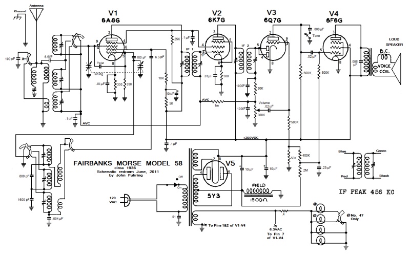 Redrawn
schematic of my 1936 Fairbanks Morse Model 58 radio.
After redrawing the diagram (shown above) I was pleased to note that the radio radio's design is very familiar to me because I could see that it incorporates design features that would be used in almost all radios during the next 25 years. There were a couple of unusual design features I wasn't immediately familiar with, but they were easy to figure out once I had the schematic redrawn. Perhaps this isn't necessary, but here's a description of the main design features: Main
design features of the Fairbanks Morse Model 58 Radio
All the tubes used in this radio had
been developed
and were made available to the market just a few months before the
radio was manufactured and so this radio
represented the very latest word in radio design for its time.
These once high-tech tubes allowed for a radio that
was simpler and better than radios which were just a
year or
two older and using less advanced tubes. I think it is fair
to
assume that my radio must have been on the drawing board sometime
before its tubes were actually
available on the market and while they were still in development
because there is so little time between when my radio's tubes first
came out and when my radio was manufactured.
By today's
standards, my radio is a rather conventional superheterodyne five tube
radio that covers the AM broadcast band and two shortwave bands.
As do all superheterodyne radios, my radio has antenna
circuits
that pick up very tiny electrical signals from the antenna, selects a
particular signal from a station I want to listen to (called 'tuning')
and connects that signal at the grid of a Mixer (or heterodyne) tube.
Not to confuse you, but this mixer stage is also called the
"First Detector" because this is where the signal is first processed by
the radio. In the mixer section, the antenna
signal is mixed (or heterodyned) with an oscillator
signal
called the Local Oscillator (LO) that is also tuned when I move the
dial. This mixing of the two signals results in a third and
lower frequency signal called the Intermediate Frequency (the IF).
The IF signal
is filtered and amplified by the IF amplifier. The signal
from
the IF amplifier is then detected by a tube called the Second Detector
and the voice and music (audio) it contains is stripped off of it.
Audio from this stage is amplified and then amplified again
by
the Power Amplifier until it is strong enough to drive the radio's
large speaker. This superheterodyne system of receiving radio
signals was invented by the brilliant radio engineer and inventor,
Edwin Armstrong in 1917, but it was not widely used until much later
and only after
vacuum tube technology had advanced sufficiently to allow the circuits
he
invented to function in an ordinary radio.
Here then is a
description of the tubes and the circuits my radio uses:
The first detector (or mixer or
heterodyne) stage
uses a 6A8 tube which
is an early
type of pentagrid converter tube. From this time on, most
radios
will be found using a pentagrid converter tube similar to the 6A8 for
its first detector tube.
The
6A8 tube was quite a sensation at the time it came out because it
combined two
functions in the same tube thus saving a lot of money and making for a
simpler and better radio. Besides doing the mixing, it also
functions as the local
oscillator (the LO). The LO
signal is created in one part of the tube, but in the same tube, the LO
signal is mixed with the weak signal that comes from the antenna.
This
off the air or antenna signal has the
music and voice we want to hear superimposed on its carrier (called a
'modulated carrier'). So, the tube is both an
oscillator and a mixer. The result of that mixing is the
creation
of
an
intermediate frequency (IF) that is used in the next stage.A little digression: The circuits associated with this first stage of my radio appeared unusual to me only because the Local Oscillator (or Heterodyne Oscillator) is configured as an Armstrong type oscillator with the +B voltage not applied to the "tickler coil" but through a 10 K resistor after being heavily filtered by a 8 mF capacitor. I've never seen anybody do that before, but it works. A local oscillator circuit using pentagrid converter tubes are always configured as Hartley type oscillators not Armstrong oscillators, so this is really unusual. Now, isn't that just really interesting? As mentioned, the next stage is the intermediate frequency (IF) stage. The IF stage consists of filter transformers and the IF amplifier tube (a 6K7). My radio's IF circuits are completely conventional and functionally identical to all radios that came later. The 6K7 tube was very special in its time because it is a variable transconductance tube (also called a remote cutoff, or a variable mu tube), as is the 6A8 tube. Those fancy terms mean that the amplification of one of these tubes can be controlled remotely by applying a negative voltage to the grid of the tube. As we will see in a minute, the negative voltage comes from the automatic volume control (AVC) circuit. Having an AVC in conjunction with these special tubes makes it possible to listen to a station who's signal is fading in and out without the volume changing a whole lot. It also enables you to tune around on the dial without blasting your eardrums if you tune across a loud and strong station. The next tube, the 6Q7, is technically known as the "second detector" because it "detects" the voice or music that is on the IF signal. It also has circuits that generate the AVC mentioned above. Actually, the 6Q7 is two tubes in one. The diode section is the second detector and AVC portion of the tube and the other section is a very sensitive audio amplifier that takes the very weak voice and music from the detector stage and boosts it up so that it can be further amplified and be heard in the speaker. The 6Q7 is another early version of a type of tube that is found in almost all subsequent radios. By the way, the diode section of this tube (the "second detector") is actually a Fleming Valve detector circuit that was developed in the early 1900s even before the days of the crystal radio. The Fleming Valve detector was so good at doing what it did, it was used in all later AM radios until tubes became obsolete. As I just mentioned, the diode section of this tube is used to generate the negative automatic volume control (AVC) voltage. The way this AVC circuit is designed is very familiar to me because this is the famous circuit invented by a young Harold Wheeler in 1925 and patented by the Hazeltine corporation around 1932. When my radio was made, it wasn't a new circuit, but it was only then becoming popular because of the availability of the new tubes that could work with it. Here's how the Hazeltine AVC circuit works: a Fleming Valve diode AM detector rectifys the carrier to produce a negative voltage in addition to producing voice and music. Strong AM carrier signals from a strong station will produce a large negative voltage while a weak carrier from a weak station will produce a very small negative voltage. If this negative voltage is placed on the grid of a variable transconductance tube (like the 6K7), a strong carrier will decrease the audio volume a whole lot while a weak carrier will decrease the audio volume by very little. This results in the sound level staying close to the same regardless of the strength of the signal. From about the time this radio was made onward, this simple, but very effective circuit was used in almost all radios. I would like to repeat that the triode (right hand) section of the 6Q7 tube takes the very weak music and voice (audio) signal from the Fleming Valve diode detector stage and amplifies it to a usable level so it can be fed to the volume control. The way the triode is configured in my radio confused me at first because it is biased differently than anything I had ever seen before, but otherwise it is the same circuit that was used in all tube radios that followed my radio. Although the triode section greatly amplifies the sound, the signal is still not nearly strong enough to drive a speaker and so the audio signal first goes through a volume control and from there it is coupled to a power pentode audio amplifier tube (the 6F6) that raises it up to speaker level. The 6F6 audio power amplifier tube is what is called a power pentode. This tube had been developed so that a single tube could provide enough power to drive a big speaker with plenty of volume. The earlier radios used lower power tubes and required three tubes arranged in what is known as "push-pull" (technically called "class AB2). With tubes like the 6F6, radios could be made much simpler, cheaper and better with just one tube in the audio output stage. After 1937 the 6F6 would become obsolete as the famous 6L6 family of beam power tetrodes would come on the market and a lower power version, the 6V6, would completely replace the 6F6. By the way, it is my understanding that the 6L6 is still in production and the last (and most powerful) of this family, the 6KD6 is the tube I use as the power amplifier in my ham radio transmitter. For simplicity and low cost, radios such as my Fairbanks needs only one 6F6 (or 6V6) tube. An audio power amplifier that uses a single tube is rarely configured to produce more than 5 watts of audio power, but for really large console radios with more than one large speaker, multiple tubes were configured in the old "push-pull" arrangement (as mentioned earlier) for dozens of watts of power. Nevertheless, for the smaller parlor radios working into a single high efficiency speaker, 3-5 watts is more than enough to fill a whole room with sound -- and loudly too. Looking back, all these circuits seem very conventional, but at the time this radio was made, it had in it advanced circuits made possible only because of the recent availability of sophisticated, high-tech, high performance, multi-element tubes. The designer(s) of this radio took advantage of the fact that these new tubes could perform more than one function and they avoided making the radio overly complicated by using no more tubes than actually needed. At the same time, other manufacturer marketed more "prestigious" and "high-status" radios that had a separate tube for each function. These much more expensive radios had superfluously high tube counts and were marketed to an upscale customer base at a higher profit margin. If you can believe it, some of the upscale radios of this era had 15 to 18 tubes, most of which did nothing but cause trouble. Certainly, many of these upscale radios did sound marginally better and there were customers who demanded the absolute best sounding radio regardless of price. These were the people who could afford to regularly replace tubes and pay a radio technician to keep their sets working properly. However, to the ears of most people, these complex radios sounded very little better than the simpler radios. When you consider that both the simple and the complex radios were used to listen to the less than superlative audio quality that is typical of an AM broadcast, it isn't surprising that most people couldn't hear any real difference between these radios. Most people considered the simpler radios, such as my Fairbanks, to be an excellent compromise between good sound quality and cost and were therefore the best value for the money. Fortunately, for the unknown person who first bought my radio, the designer(s) of my Fairbanks Morse decided to use the latest tube technology and by doing so, they made a simpler radio that not only had excellent performance and was easier to maintain, but it saved that unknown first customer a lot of money and thereby gave that customer a greater value for his/her money. By designing their radio simpler, cheaper and better than the more expensive radios, they also saved ME a lot of time, effort and expense when I restored my radio. In short, the designers of my radio back in 1935 were practicing the very best of what today we call modernity. This radio was a good example of the concept of modernity put into practice. I think it is very ironic that my simpler Fairbanks Morse radio is today (for me anyway) much more desirable to own than the more upscale radios of the same era. The
way this radio differs from later tube radios
For me, one of the things that is
most unusual
about this radio is the electromagnet that is used to generate a
powerful magnetic field that operates the speaker and doubles as
a
choke
coil to filter the hum out of the power supply. This was a
very
old
fashioned arrangement and it was used because electrolytic filter
capacitor technology
had not been well developed and so those capacitors were huge and
expensive. Back in those days, it was cheaper and better to
use a
big choke coil and to build the choke coil into the speaker where it
could be hidden away. Of course, this would introduce hum
into
the speaker, but that could be overcome by using another unusual thing
I'd never worked with before,
a hum
bucking coil (the
B.C. coil shown in the schematic). A few years later, new
capacitor and tube technology would make it possible to make a similar
performing
radio with a much simpler, lower voltage power supply.Speaking of power supplys, my radio's power supply is not simple or low voltage. It produces 250 volts DC using a large power transformer and a full wave rectifier (the 5Y3 tube). Using an expensive transformer makes for a safe radio and therefore no back panel was needed to protect people from dangerous and painful electrical shocks. Later, with the elimination of the transformer and the development of tubes with high voltage filaments, the (in)famous All American Five (AAF) configuration was developed. These new AAF radios would be smaller, much cheaper to manufacture and much more affordable. However, cheapened up the way the were, they would not have the quality sound of the older radios. The worst thing about the newer "All American Five" radios was that they were and are much more dangerous than the older radios. I wonder how many people have been electrocuted by small transformerless radios they foolishly placed in their bathrooms or next to the kitchen sink? By the way, 250 volts of direct current (DC) is exposed under the chassis of this radio where only a radio technician can possibly encounter it. As bad as it seems, this 250 volts is much, much safer than the 120 volts of alternating current (AC) that appears on the very chassis itself of the AAF radios. Thomas Edison noticed it back in the 1890s that AC voltages are about 10 times more dangerous than DC voltages and so, even if a radio technician should accidentally touch the 250 volts deep inside the underside of the radio, it would be painful, but not very dangerous. I'm certainly living proof of that because I can't tell you how many times I've been "bitten" by high voltage DC power supplies while working on tube radios. Finally, the thing I found very different from anything I had ever worked on before was the way the 6F6 and 6Q7 tubes were biased. Usually the second detector's triode section is self biased with a high value grid resistor (like ten megohms) and the audio power tube is biased with a resistor and electrolytic capacitor in the cathode circuit. Well, in those days, electrolytic capacitors were big and expensive (as already noted) and since there was already a large negative voltage available at the choke coil, all they had to do was make up voltage dividers using standard (and cheap) resistors and they would have the voltages necessary to bias the tubes properly. Because of the way the original schematic was drawn, at first I couldn't quite figure out just what was going on, but after redrawing it, I could see and appreciate the simple, but clever way they biased those tubes. As amazing as this 1930s technology is and how it seems so wonderful to me, the sad truth is that it now so terribly old fashioned and obsolete and I wonder how long it will be before there is nobody left who understands it anymore. The last of us vacuum tube dinosaurs will soon be extinct and then these old radios will truly be a thing of the past. With the end of this technical digression, you might want to read about how I removed parts, put in new parts and got old frozen mechanisms working again. Rebuilding
the old radio
One thing that really threw me was the
old
fashioned way of assigning values to the resistors. This set
uses
very old fashioned resistors (and all of them are still good after all
these years). The colors have faded and the old fashioned
color
scheme is
such
that I have found it pretty near impossible to tell what their values
are supposed to be. What I really found confusing was how
they
were assigned
values in the parts list. Ordinarily, a resistor that has
10,000
ohms of resistance is written as 10K, a resistor that has 1,000,000
ohms of resistance is written as 1M. In the old parts list of
this radio, 10,000 is written as 10M and 1,000,000 is written as 1
megohm which, to me is exactly the same thing. Since
resistors
above one or two megohms are
very
rare (there is only one in this radio), when I saw resistors labeled as
500M
and 60M and that just astounded me really threw me into a loop.
Five hundred megohms!?!
Sixty megohms!?! WHAT?? THAT JUST CAN'T
BE!! This had
me worried. I sure hoped that none of the
resistors were
bad, because in today's world, it would be virtually
impossible to
find replacement resistors
with values like that. In fact, I have no meters that can
measure
anywhere near that
high so it would be impossible to test them. A mystery that was nearly a show-stopper Before I began working on the radio or even take it out of the wooden cabinet, I began formulating a plan to redesign all the circuits to operate with "normal" values of resistance and replace all the old resistors with their impossibly high resistance. Thank the gods that it dawned on me that maybe the famous Rider company had made a big mistake and had really meant to write 'K' for 'M.' In the parts list, when I scratched out 'M' and wrote in 'K', all the circuits started to make sense. When I opened up the chassis and took direct measurements of the resistors with my ohmmeter, sure enough, they were Kilohm and not Megohms. What a relief, to know that my radio used ordinary resistors after all. On doing a little research (thank you Internet) I discovered that in the really old days of radio, M (as in Roman Numerals for 1,000) was used to indicate 1,000. Who would have thought it, but when you think of it, today we write the year 2011 as MMXI. We don't write today's year as KKXI, so perhaps I should have known better and not have scared myself as I had. What a lot of time I wasted pondering this foolish little mystery, but I am so glad that I finally figured this out because I was just about to start yanking out and replacing resistors and that would have lead to a real disaster. I shudder to think how many hours I would have spent trying to recalculate values for voltage dividers, bias resistors, anode resistors and such things as those. Horrible
old parts I ruthlessly yanked out
Well, on the following Monday evening
after the
radio arrived and after I had obtained a schematic diagram for this
radio, I
took the
chassis and the large, heavy old speaker out of the cabinet.
Once
out of the cabinet, I started to pull
a pile of horrible looking old parts out of the chassis. 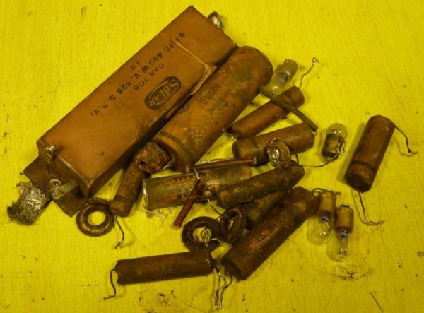 Horrible old parts I pulled out of the radio. I had no idea what the lamps were, so I replaced them with lamps I knew wouldn't put another burn mark on the dial. 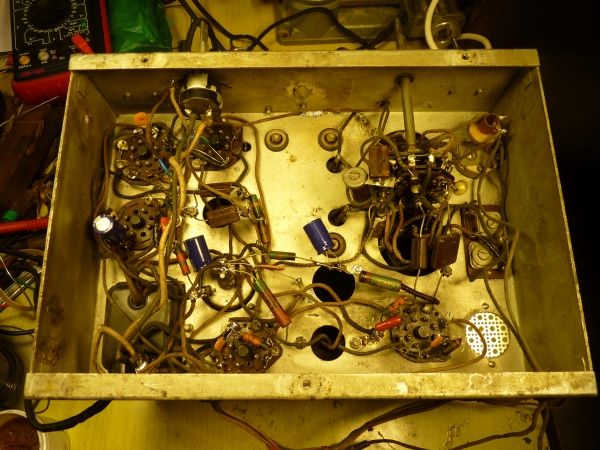 With the large old parts stripped out and the tiny new parts put in, the chassis looks bare. One of the genius of using tubes is that there are so few components that are needed to support them. With the exception of the paper/wax and electrolytic capacitors, all the original components are as good as the day they were manufactured.
My town's
Electronics Parts Supermart didn't open
until
the following Tuesday, so that morning there I was with a shopping
list consisting of the ten ceramic and mylar capacitors and three 10
MFD, 350 volt electrolytics I'd need. I
bought a
pile of new parts much smaller than the pile I had removed. I
soldered
the new parts into the chassis that evening and, nerd that I am, I
had a very entertaining evening doing that and watching it all come
together.
The
few parts I actually needed
to make the radio work again As it turned
out,
the seven 75 year old silver-mica capacitors were still in excellent
condition so I left them alone. It has been my experience
that
silver mica capacitors never need replacement. Of course, the
trimmers and the air variable capacitors were all
as good as the day they were made and all the original resistors were
good too (as they almost always are), so actually I had to
replace only a dozen or so small
parts. Everything I needed to spend on this radio came to
less
than
$20. Not withstanding how little they cost, the ceramic and
mylar
capacitors that I put in this radio are far, far superior to the old
paper/wax capacitors and they should last forever. With the
exception of the electrolytic capacitors and the tubes, I
figure
that this radio should still be
playing 100 years from now. Hopefully, the old radio will
still
be a cherished antique while what was once me is long forgotten and
reduced to mere dust.
Clues
to the repair history
While I was at
it and while I had the
guts of the
radio exposed, I looked for clues regarding the repair history of this
radio. By
looking at the various levels of workmanship and especially
noting
the style of
replacement parts they used at various times, I could tell that this
radio had undergone major
repairs on at least three different occasions and one final attempt was
made recently. First, there was evidence
that
an electrolytic capacitor was replaced, probably in the late 1930s when
those types were a little smaller than original, but still quite large.
Next, it
appeared that two more electrolytics and at least one paper-wax
capacitor were replaced in the early to mid 1940s. Judging
from
the type of potentiometer that was
used, it appears that the volume control was replaced in the late1950s.
It also appears that the power amplifier tube was replaced by a
slim "modern" one probably at that time too. Finally a modern
"antique style" power cord was very inexpertly installed not too
long ago in a futile attempt to get the set working again, but by that
time the tuning mechanism was frozen and all the capacitors were too
far gone to have allowed the radio to function anyway and so I'm sure
whoever did the work realized he was over his head and just sold the
radio as-is.
Final
steps necessary to get the radio working after more than 50 years
By Wednesday I
had the frozen tuning
mechanism
freed up,
the tuning deck remounted on new rubber grommets and the whole dial
mechanism working again.
Another thing that was nearly a show-stopper was the fact
that
the very special belt that operates the dial mechanism had rotted away.
I tried making up a belt out of multiple sections of heavy
string, and it did work -- sort of, but I really needed a new drive
belt for the dial mechanism. Wouldn't you know it, the
Internet
came to my rescue again. After searching around a bit, I
found a
company that makes drive belts for all old radios. I sent off
for
one and a few days later I had a belt made of a high-tech material that
should last forever and with it installed, the operation of my dial is
silky smooth.
I cleaned up 70 years of grime inside and outside the cabinet and chassis and, if I may say so, the beautiful dial of this old radio is ever so much more beautiful now that you can see it thorough the fogged up window. 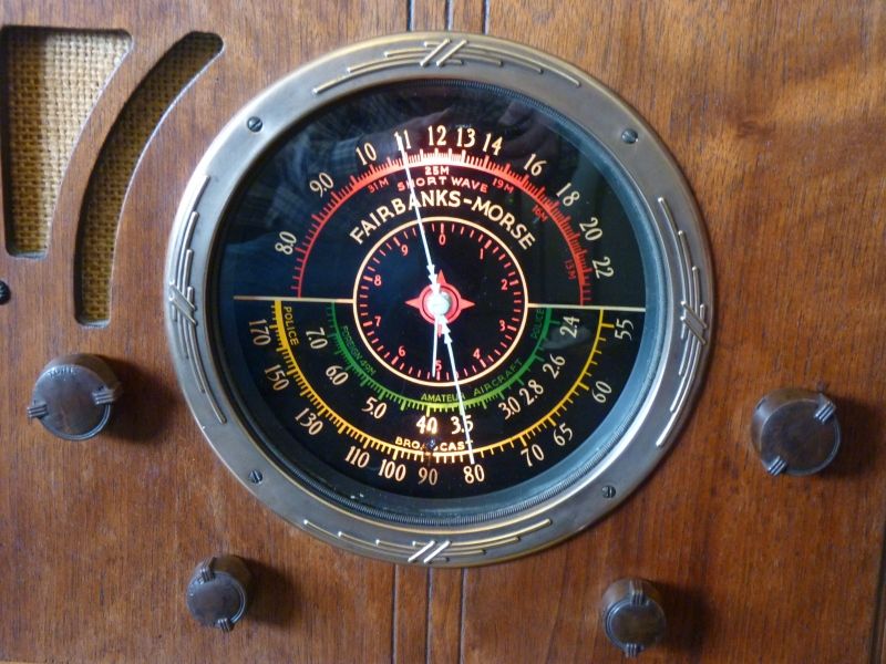
On Wednesday afternoon after I had all the electrical, mechanical and cleanup work done, I plugged in the radio. As always, I had compared the schematic diagram with every circuit in the radio making double and triple sure that I had everything installed correctly and that everything was as it should be. I turned on the radio for the first time in maybe 50 years or more with all the confidence that comes with having done all my homework and after a short warm-up, I could hear a normal quiet hiss, but no hum,and nothing smoked. I then turned the dial to the first AM station that I came to and and a beautiful, mellow sound came out of the speaker - probably for the first time in 50 or more years. I wasn't expecting all the old tubes to function, but they did, and perfectly. I then connected the antenna lead to one of my outside antennas and that evening I listened to shortwave broadcasts from all over the world. Outside
wire antennas
By the way, it is my firm opinion that this radio
was most likely
targeted for
sale to rural customers and people who were familiar with the Fairbanks
Morse
name. Fairbanks Morse was a major supplier of rugged,
reliable
and affordable
agricultural machinery and radios marketed by them would naturally
appeal to farming people. Living in the country, far from
broadcast
towers, a rural customer needed a radio that could receive broadcasts
from
long distances and therefore the Fairbanks Morse company did not bother
to include a built-in loop antenna, which is
useful mostly in urban areas. To receive both the AM
broadcast
band and the two short wave bands, this radio has always needed some
kind of
external antenna and, in fact, farm houses of that era
generally had long, high wire antennas just for this reason.
For
local AM reception, a short 1 or 2 foot piece of wire is all that is
necessary, but for long ranges, a radio of this sort really shines when
you connect up a long antenna that is 30 feet or more and the longer
and higher you make it, the better.Now,
where was I?
To my utter amazement, I found that all
the tuned
circuits in the RF and IF stages were still in perfect alignment even
after 74 years and there was no adjustments I needed to make to improve
the radio's already excellent performance. The
dial
calibration is right on the money and the tuning is sharp and sensitive
with more than enough volume even on the weakest signal.
There is
nothing more I need to do with this radio except perhaps to restore the
cabinet to look a little newer. But perhaps I should leave it
alone because the first thing that everybody says who have seen my
radio say
is that it looks like a modern reproduction and not like they would
expect an old radio to look.What
have I done this
time?
I think I
done a bad thing George. Oh my, I may have
desecrated my old radio by doing something an antique purist should
never do. Yes, I added a modern BFO to my old radio.
This is another technical discussion and if you are not
interested in such things as BFO's, you might want to skip
this section. Of course, this radio was designed for home entertainment and to listen to AM broadcasts from all over the world. It was designed before single side band (SSB) broadcasts and not meant to receive Morse Code so it did not have a beat frequency oscillator (BFO). Only military and certain specialized amateur radios had BFOs back in those days, but today there isn't much left of the once glorious programming that used to be on short wave and so a BFO is now a very desirable thing to have. I greatly expanded the usefulness of my beautiful old Fairbanks Morse by adding a very simple, very inexpensive, but very effective BFO to my radio and I did it without altering the fine appearance of the radio or even its basic wiring. One of my my unbreakable rules when restoring this radio was that no modification would be visible, I would not, under any circumstances, desecrate the beauty or originality of the old radio except in ways that could not be seen and the modification could be removed in an instant and without rewiring the radio. In all regards, my BFO module satisfies these restrictions. What's really neat about what I've done is that I didn't touch any of the existing circuits in any real way and what I've added is so unobtrusive, you'd never know it was in there. To remove the BFO, all I'd have to do is cut out two new wires and simply lift the little module out. Within a minute or so, the radio would be exactly as it had been originally designed. I wouldn't even have to replace the new tone control switch I put in, but I will keep the old one just in case I want to put the radio back exactly as it was. I installed the device as an experiment to see if having a BFO would enhance the operation and enjoyment of the radio and in that, I think I have succeeded very well. I can truthfully say that the BFO works splendidly and I'm pleased to be able to listen to single side band (SSB) Morse Code broadcasts that were always there, but until now, unavailable. With this little device I'm able to expand the usefulness of the old radio beyond the dwindling AM broadcasts it was limited to. The BFO circuit is built on a tiny perf board and mounted next to the IF tube using the screw and nut that fastens down the second IF transformer. The DC voltage to power the unit is from pin 8 of the 6K7 IF tube. Pin 8 is the cathode circuit and develops about three volts across its bias resistor. Because the BFO module draws so little current (about a half a milliamp), it effects the bias of the tube very little when the BFO is turned on and not at all when the BFO is turned off. To provide on/off control of the BFO, I replaced the two position tone control switch with a three position switch. The first position is like before with the audio at full range, the second position is as before giving more bass to the sound, but the third position disables the automatic volume control (the AVC) and turns on the BFO module. Looking at the front of the radio, you'd never know it had a BFO and until you place the tone control all the way over, it works and sounds just as before. 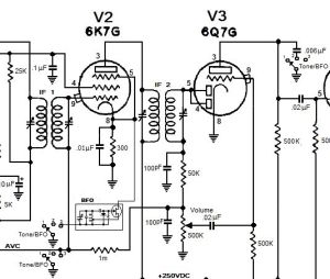 Diagram showing the placement of a little FET BFO module and the three ganged Tone/BFO Control switchs. The first two positions control the tone, the third position turns on the BFO. 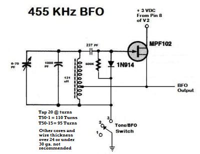
This little module produces a clean 455 KHz carrier that mixes with SSB and CW and turns them into intelligible signals surprisingly well. Because it is tied to the cathode of the IF tube, there is no need to couple the output signal to any other part of the radio and so the wiring and installation is simplicity itself requiring nothing more than the module, three wires and a new wafer switch. The new wafer switch has two extra circuits the old switch didn't have. When the BFO is turned on, one of the circuits disables the AVC line so that the BFO's signal doesn't cause the gain of the mixer and IF to be reduced and the other circuit provides a ground (or return path) to turn on the module. That's all I had to do.
Normally I do things very
conventionally and the
conventional way of wiring in a BFO is to take its output and couple it
to the grid of an amplifier so that it will mix with a signal.
Connecting the drain of the FET to the cathode of the IF tube
is
so utterly simple, but something that hadn't occurred to me before and
I didn't know if it would work very well. In fact, this way
of
powering the module and injecting the BFO signal at the same time has
just amazed me by how well it seems to work. Last night I
listened to Single Side Band broadcasts on 80 meters and all
the
signals, ranging from very strong to very weak, sounded good, really
good. To tell the truth, I am extremely pleased with this
little
modification and I consider it a positive improvement to the usefulness
of the old radio.
Yes, the shortwave bands are only a
shadow of
what they once were, but with this BFO, much more
is suddenly made available to listen to on shortwave. If you
have
one of these wonderful
old radios, you might consider adding one of these circuits.
Nobody will ever know you have put a BFO in there just by
looking
and the radio
will work and sound exactly the same on AM, but by doing so, you will
have a more useful radio. Of course, listening to most hams
talk is about as much fun as watching paint dry, so you will have to
decide if adding a little BFO is really your "cup of tea" or not.
If you do decide you want to add a BFO to your old radio and you
need more advice than what's here, drop
me a line and maybe I can help.
Conclusion
The
life and times of Depression
Era radios
I should mention though that these radios were all hand wired and by today's standards, extremely expensive. My guess is that a new radio, such as my Fairbanks Morse, sold for the equivalent of maybe $1,000 to $1,500 in the mid 1930s, maybe more. These were a major purchase (next to a house and car) and so most people had only one (and room for only one) radio back then. Having a beautiful looking radio (with such a nice dial too!), a radio that sounded so nice and could tune in the whole world, must have been a great source of pride, in addition to its obvious entertainment value. I can only imagine how excited, pleased and proud the person was when he or she first took this radio to their home and plugged it in for the first time. I'll bet they invited the whole neighborhood in to listen to it. The voice of President Roosevelt must have sounded many, many times in the very speaker I'm listening to and the electrical undulations of his voice must have modulated the electron stream of many of the very tubes that are still in this radio as he gave his comforting and intimate "Fireside Chats." I can just imagine the whole family sitting around such a radio at night listening to this or an exciting drama, comedy show or a news broadcast of some important event - like a King's Speech - while during the day the radio would fill the house with the latest big band and jazz music or a baseball game while informing everybody within earshot of the advantages of Palmolive Soap and Wrigley's Gum and how lives are ruined forever by not using Listerine for their bad breath and the efficaciousness of Doctor Vornoff's Monkey Gland Treatment and how if you drink Ovaltine before going to bed, it will help you sleep and you will wake up GAY in the morning and how more doctors smoke Camel cigarettes than any other brand. There are many beautiful old radios that date from this era, but in my opinion, my radio has one of the most beautiful dials of any of those radios. I think that only the Zenith radios had dials as pretty as mine. You may have noticed that I'm calling my radio "The King's Speech Radio" because it is altogether possible that the abdication of King Edward ("I can't be King without the support of the woman I love") was listened to, via BBC shortwave, the December following my radio's manufacture and then later little brother Bertie's famous speech was also listened to, again via BBC shortwave, three years later on September 1939 as Britain began the second great war with Germany. I think I'm going to add "Fireside Chat" to the name of my radio because it is almost certain it was used to listen to those too. I love these old radios for their beauty, their interesting technology and the fact that they are an important and key artifact of our culture and civilization from a very important time in the history of the world and my country. I don't know if my parents and grand parents owned this particular model of radio back in the 1930s, but whatever they owned, it was something very similar. THE END
Having arrived this far,
obviously you have a superior attention span and reading ability that
far exceeds that of the
majority of web users. I highly value the opinion of people such as yourself, so I ask you to briefly tell me:
If you have an antique AM radio and you need something decent to listen
to, perhaps you should buy or build your own
 Low Power AM transmitter Recently I found and restored a 1938 Crosley Super 8 radio that was from a posponed repair job 50 years ago  Please go to my Crolsey Radio Story There is another story of how I recently restored a 1930s that my parents gave me when I was a kid
 Please go to my Troy Radio Story For a simplified, but more in depth explanation of how this and similar radios work, you might be interested in 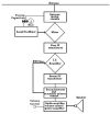 An essay on the Armstrong Superheterodyne Radio Principle I
have a lot of other old radio stories on my website
 For
other stories and things,
|