|
The
Echophone EC-1 Radio Project
The history of the famous World War Two GI's radio and how I picked up one cheap and restored it. A comprehensive story containing historical, educational, technical and biographical elements & opinions by John Fuhring Introduction
The following
is the story of how I bought my EC-1 and how I restored this radio that
was
originally sold for scrap. It is a story told as a STORY and
not
just as a restoration article. You can skip around and
concentrate on those things that interests you if you like. I
wrote this story for my own
amusement and in a style without regard to the rules of popular
writing, but I sincerely hope that you will find it entertaining and
perhaps you will find something in it that is useful.
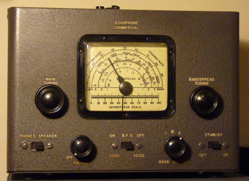
The EC-1 in its Historical Context The original EC-1 was the GI's radio of World War 2 and it was manufactured by the Hallicrafters company under the brand name "Echophone Commercial." It began production toward the end of 1940 and continued in production all through the war. This model radio was about the only commercial, non military radio that the government allowed to be manufactured during WW 2 and they did it for morale purposes, that is, to provide lonely, homesick and bored servicemen with entertainment. These rugged little radios have good short wave circuits so the servicemen and women could listen to shows, music and war news no matter where they were in the world. The EC-1 sold at a "reasonable" price of about $20 (about a month's pay). Actually, for this quality of radio, $20 was a very low price and a lot of GIs got to own them either by buying them outright or receiving them as gifts. The EC-1 radios were marketed to the GIs directly and through their families to be given as gifts. Ads for the radios appeared in magazines with a rather over the top campaign featuring a Private (later corporal) Hogarth. Hogarth was always shown as a hopeless nerd with coke-bottle glasses, but very popular with pretty girls who wanted to listen to his radio. Today we know better than to believe that a nerdey guy could attract girls with a short wave radio, but those were innocent times. 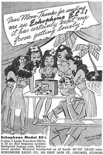 
Some of the
advertisements that
appeared in magazines were pretty silly
suggesting that the GI owning one of these radios would become really
popular with pretty young women regardless of how big a nerd he is.
My experience in life has taught me that women are anything
BUT
interested in a shortwave radio and that a nerd is a nerd is a nerd
whether or not he has an EC-1.
Still, parents wanted to give their serviceman something
useful
and entertaining and these radios were as nice a gift as it was
possible to give.
Most of the ads for the EC-1 directed to the GIs had a rather in-your-face sexual theme as the following suggests: 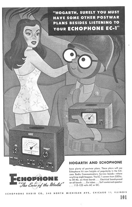 As a nerd myself, I am rather proud of Hogarth for preferring his EC-1 to the sexy young woman, ha, ha. 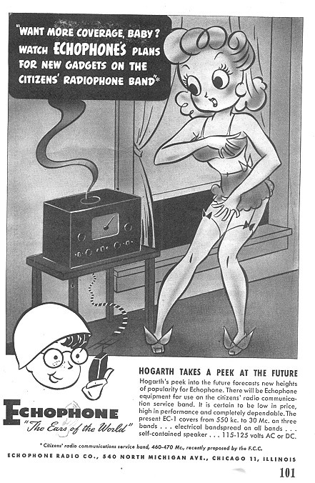 Hallicrafters calls it "peeking" but it's really more like voyeurism 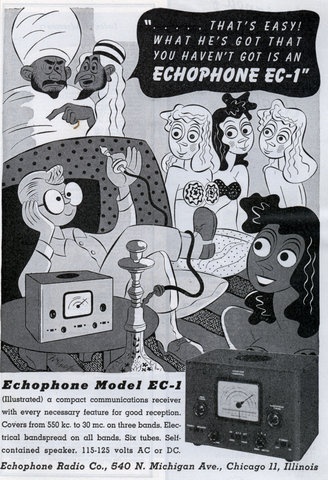 Lots of wealthy Arabs have harems, but not one GI with an EC-1 and who hasn't a single oilwell to his name does.
This appeal to
sex must have
worked to sell these radios during that unsophisticated age, because
these ads appeared all throughout the war.
Some of the ads were downright racist reflecting the stereotyping of the Japanese enemy so common in this country at the time. 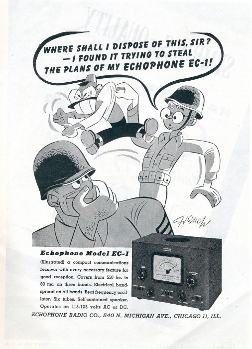 Notice the big glasses, the slant eyes, the huge front teeth and holding the nose at the smell of "the stinking Jap."
What's ironic
about this
advertisement is that the EC-1 radios used early 1930's technology and
the Japanese military radios were far superior to these little GI
radios. No Japanese spy or soldier would give a hoot about
its
"secret plans." If anything, a Japanese soldier would have
liked
to capture one so that he too could listen to Tokyo Rose.
From
what I understand, Imperial Japanese soldiers were treated
like
dirt, absolute dirt by their officers and I'm sure they were forbidden
to own radios. Any Japanese soldier caught with one of these
radios would have his head cut off immediately by any number of
officers who were only too willing to try out their Samurai Swords.
What's also interesting to think about is how, less than 25 years earlier, during World War One, this same radio, with its sensitive and sophisticated multi-element vacuum tubes and superheterodyne design, would have seemed like it was from another universe come down on a space ship. These little EC-1s were that much more advanced than the crystal and Fleming Valve radios in use during The Great War. There were some experimental Armstrong regenerative radios during that time and this same Edwin Armstrong was developing his famous oscillator and heterodyne circuits that would later show up in this radio, but even the best military radios of 1914-1918 could not come anywhere near the performance of the little EC-1 radio - and that is the understatement of the century. How
I got a Second World War EC-1 Radio for Myself
I really didn't need
this radio. I already
had an EC-1b that
was
manufactured
immediately after the
war's end,
but I wanted a genuine WW 2 model, so I when I saw this on eBay being
sold for parts only, I put
in a bid and won it for only $15. It was a wreck all right.
The
dial was badly peeling and unreadable, the paint on the inside and
outside of the case was terrible and the back panel
was missing. There were a lot of other internal problems with
this radio too that made it a candidate for the junk pile, but I was
pretty sure I could restore it and the price was certainly
right. When I opened up my radio and took a good look at the internals, it was obvious that two different people had tried to repair it and the last person had wired parts of it incorrectly with very inexpert soldering. All evidence, deduced from the style of the replacement parts, indicated that the radio had not worked since the mid 50s. AN IMPORTANT SAFETY WARNING TO
ALL EC-1
OWNERS!
IF YOU OWN ONE OF THESE RADIOS
OR ANY "ALL
AMERICAN FIVE" RADIO WITH A "HOT" CHASSIS,
PLEASE READ MY SAFETY WARNING.
THESE RADIOS ARE VERY LIKELY TO PRESENT A DEADLY SHOCK
HAZARD AND THEY SHOULD NOT EVEN BE PLUGGED IN, MUCH LESS WORKED ON
UNTIL THEY ARE REWIRED FOR SAFETY. THE REWIRING IS VERY
SIMPLE,
VERY CHEAP AND VERY EFFECTIVE, SO PLEASE TAKE THE TIME TO MAKE THIS
MODIFICATION.How
I Restored My EC-1
With any project of
this type, the first thing one
needs is a good schematic. You need a good schematic to work
to,
to check any work done by others
and to confirm that all replacement components and changes have been
wired in correctly. Over the years, it is
impossible to know who did what to your radio and therefore it is
necessary to check every circuit against a good schematic. If
something is still wrong and
the radio won't work, a good schematic is invaluable for
troubleshooting and discovering what the problem is. I began the task of creating a good schematic by capturing fuzzy and hard to read schematics off of Internet sites. By the way, up until the fantastic development of this greatest factor in the spread of knowledge mankind has ever known (the Internet), schematics for these old radios were just about impossible to find. They certainly weren't available to just anybody back in the early 1960s when I first started working on these old radios. After I had captured a schematic off of the Internet, I began to redraw it for clarity using the Paint program that came with my PC. I also went to the radio itself to double check any circuits I wasn't sure about. I then modified the drawing I had created to show certain changes I made to the radio and to show how the radio was really wired. 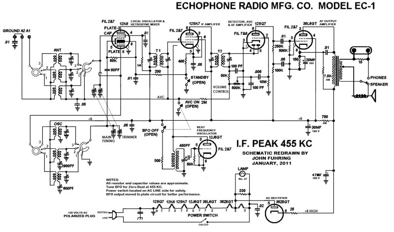
A Little Essay on What Schematic Diagrams Are and Are Not
For those who
have not had experience reading schematic diagrams, please be aware
that
a schematic is only to tell the technician HOW THE RADIO WORKS and not
meant to tell exactly
how the radio is wired. The schematic is ELECTRICALLY
correct, but how everything is actually hooked up is another
matter. On the schematic it appears that a wire goes from
component to component, but that is rarely the case in real life.
As radios are actually wired, components are usually mounted
on
termination points that are jumpered to other points. These
termination points may be terminal strips or they may be
unused pins on tube sockets (that are almost never shown).
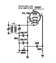
For
example, look at the AC rectifier tube in the in the lower right part
of the diagram above. You will see that a 25 ohm resistor is
connected to
pin 8 with the other side of it going to the 47 MF capacitor.
Actually, the other side of the 25 ohm resistor goes to
unused
pin 1 of the same
socket, pin 1 is then jumpered over to pin 4 and from there the 47 MF
capacitor is
connected. It is up to the technician to know enough about
how
all this stuff works to figure out for himself and trace out for
himself
the actual wiring from the schematic. Where the
schematic equivalent and the actual wiring don't match, you have a
miswire and you must fix it. If you find these diagrams
confusing,
you must realize that reading and understanding what is
going on as shown by the schematic diagram is a skill that took many of
us years
and years and many hours of learning to master and you won't learn
it overnight. As with any journey worth taking, what you see
and
learn while getting there is
the best part.
A Little Essay on how These
Radios Work
A technical side note off of the subject of the story just in case you are interested Armstrong noticed and wrote a scientific paper on how it was possible for a radio signal to be heard on an entirely different frequency by a receiver if a nearby oscillator circuit was nearby. In other words, if a station was radiating a signal on 300,000 cycles per second (today we say Hz for short) and if a oscillator is tuned to 400,000 cycles, the radio station will be heard at both the original 300,000 cycles AND at 100,000 cycles. A lot of people had already noticed that and for them it was nothing more than an annoyance, but to Armstrong this opened up a world of possibilities. If he could take one of those newfangled British Type R Valves and cause it to oscillate by building a circuit he had invented years earlier in 1911, he could mix its signal with a weak signal from a distant radio station to get a signal that landed in a more useful part of the radio spectrum. For example, if the radio station was broadcasting at what was then called "the short wave band" up around 1,500,000 cycles per second, it was difficult to tune in just that one station and not have a lot of nearby stations also get into the radio. At that frequency and higher, it is really difficult to make radio filters, but at lower frequencies, say 100,000 cycles, really sharp filters are easy. By simply mixing the stations's 1,500,000 frequency with a tunable (Armstrong) oscillator that is operating at 1,400,000 cycles, a new frequency of 100,000 cycles is produced and can be fed into a narrow filter so that only the one station is heard and all other interference is blocked out. This new frequency he called the Intermediate Frequency or the IF and the series of filters and the amplifier tube to make up for the losses going through the filters he called the IF amplifier. The whole arrangement, including the filters (called IF transformers) and the amplifier tube is what is called the "IF strip." By the way, the filter transformers (or cans) I'm talking about are composed of a resonant circuit made from a coil and a capacitor and precisely tuned to the IF frequency. The signal in this so-called "tank" circuit transformer coupled to a second tuned circuit within the can. If it is the 1st IF transformer, the output goes to the IF amplifier tube, but if its the 2nd IF transformer, it goes to the "detector" tube. Arranging transformers like this (called "loose coupling") makes the filter very narrow which is what you want. The amplified and filtered signal from the IF strip can not be heard because its frequency is beyond the range of hearing or, in other words, it is supersonic. To turn this supersonic radio frequency signal into something we can hear, it is fed into a detector tube (usually a simple diode like a fancy version of a crystal radio) where sound is recovered and then another tube where the audio (sound) signal is amplified and finally into a power amplifier tube where the sound can drive a loud speaker. The earliest superheterodynes used low frequencies, but later frequencies around 455,000 cycles (455 kilo HZ) became standard for various technical reasons. You might ask, are there any other IF frequencies that will work and the answer is "of course." In my home made ham radio, I use an IF of 9,000,000 cycles (9 mega Hz), but way up there an ordinary radio frequency filter, such as Armstrong used, just won't work. To make my radio work with such a high frequency IF, I had to use a very sharp "crystal filter" that relies on the very narrow filtering provided by the mechanical vibration of thin strips of quartz. By the way, it is a tiny version of those thin strips of quartz vibrating at a very precise rate that is the heart of the quartz movement in your watch and why even the very cheapest watch today keeps many, many times better time than the most expensive watches did when I was a kid. In my EC-1 the leftmost tube (12K8) is the mixer + oscillator tube. The upper half of the tube mixes the signal with the frequency produced in the lower half of the tube which is configured as an Armstrong oscillator. An IF signal is created which is filtered by the 1st IF transformer and amplified by the next tube to the right, the IF amplifier (12SK7). The IF signal is filtered even more by the 2nd IF transformer and then the signal goes to the left hand diode section of the next tube, the detector tube (12SQ7). The audio recovered from the signal is amplified in the right half of this tube, goes through the volume control and then drives the audio power amplifier tube (35L6) which then drives the loud speaker. Of course, the EC-1 also has a BFO or "beat frequency oscillator) tube (12J5) and what it does is create a IF signal that is very, very near the signal's IF frequency so that when they heterodyne or "beat" together, a "audio heterodyne" is produced so that a whistling sound can be heard. The BFO is necessary to provide this service otherwise Morse Code (called CW) and single sideband voice signals can't be heard properly. I have also written an essay on the superheterodyne and go through the components step by step. The essay (and lots of other things) may be found in the radio section of my website. If you are interested, you might want to read that essay too. Well, if you are still with me, let me get back to the story. Completely
Removing the Chassis From the Case
After I had
a good schematic to work to, I
began the manual task of restoring my radio. Because of my
radio's poor physical condition (it had been sold for 'junk' only after
all), I need to completely disassemble it down to the last screw and
rivet so I could have access to everything.As with my EC-1b, I had to grind out the rivets that prevented the chassis from being removed from the case. When I had the chassis separated from the case for the first time since my radio was built, I discovered a broken wire, well hidden in front of the band switch, that had never been repaired. This hidden defect would have prevented the AM broadcast band from working and therefore the radio must have been used exclusively for shortwave listening. Why it had never been repaired I can only guess. My guess is that the owner either didn't want to spend the money to have it fixed or none of the shops he took it to could find the problem -- maybe they didn't have a good schematic like mine to work to. It is altogether possible that the owner didn't care about the AM band and was interested in listening to shortwave only. If this radio had been part of an airfield or air search and rescue organization, the AM band would have been superfluous anyway.  The chassis removed from the case. I have no idea how one could replace the string that operates the tuning capacitors with the chassis attached to the case. Replacing the string that operates the main tuning is very simple, but the bandspread string takes a lot of thought and practice. The tuning deck was remounted with rubber grommets cut to make them the right size. Replacing
Components
I
fixed that broken wire on the band switch and I replaced all the old
paper and electrolytic
capacitors. All the resistors (except the 330 ohm) and the
three
silver mica capacitors
were
in good condition, so I left them alone. Unless a resistor
shows
signs of serious overheating, it is my opinion that it should be left
alone as none of the resistors values are critical and they don't vary
all that much over time. The 330 ohm
resistor is only a 1/2 watt unit and it usually burns up when the lamp
burns out. If you replace the 330 ohm resistor with a two or
three watt unit, you will never have to worry about this resistor going
out again.By the way, this model of radio was designed to use low cost components and therefore there are only three silver mica capacitors in the whole radio. Even these silver mica capacitors are in circuits that are not in any way critical. One of the silver mica caps (the 50 PF) is used for coupling and the other two (100 PF) are used for bypassing. All capacitors may be replaced by ordinary disk ceramics -- yes, even the silver mica caps. Replacing silver mica with silver mica is better, but I doubt you would be able to notice any difference in performance or any frequency drifting if you used ceramics. By the way, the only reason silver mica capacitors were used in 1940 was because low value capacitors (50 to 100 PF) were only available in silver mica. Speaking of capacitors, for this radio I used disk ceramic capacitors I already had and they work just great. My last rebuild was a 1937 farm radio for a friend of mine and for the first time I used metalized mylar caps. Too tell the truth, I liked working with the mylar caps better because of the long axial leads more easily span the large spaces left after the old paper/wax caps are removed. With regard to performance, I don't believe it makes a lick of difference what kind of cap you use as long as it's not a paper/wax cap. While I'm on the subject, let me suggest that you make up a list of all the caps you will need to replace, send for them and then assemble everything you will need into a kind of a kit. Your kit should also include gripping tools (I use hemostats), a good soldering iron, solder-sucking braid (I also use a vacuum solder sucker), a jar of extra rosin flux (I don't know what I'd do without my extra flux) and a roll of electronics grade rosin core solder. Once your kit is assembled and you begin your work, I think you will be amazed how quickly the work goes because these radios are so very easy to work on. For safety sake, I put in a polarized plug and connected AC Neutral to the chassis as described in the safety page (which I urge you to read and follow). I relocated the power switch so that the AC Line voltage switches the filament string and rectifier circuits on/off all as described earlier in the safety section. All the insulating grommets were replaced so that there was no electrical connection between the chassis and the outside case besides a .02 MFD bypass capacitor and 470 K resistor shown in the schematic. The rubber washers that were used to mount the tuning capacitor deck were in terrible condition and it is impossible to obtain exact replacements. For a while I thought remounting the tuning deck was going to be a "show stopper" but by cutting down ordinary rubber grommets to fit, I got the deck mounted perfectly. Getting
My EC-1 to Operate for the First Time in 50 Years
When I turned the
radio on
for the
first time in probably 50 years, I was gratified, but not too surprised
that it immediately came to life because I had done my homework and had
checked and rechecked every circuit and wire against the schematic
before plugging it in. As I tried to tune in
stations on the AM band, I had a feeling of great disappointment
because the radio performed
very poorly and sounded very weak. I thought I was going to
have
to buy a new tube or two, track
down some bad resistors and generally spend a lot of time
troubleshooting the set, but a simple IF
alignment really brought the little radio alive. All of a
sudden,
this old radio was "hot," bringing in stations loud and clear.
Somebody, a long time ago, must have been messing with the IF
transformers in an attempt to get the radio working and had them badly
out of alignment. Once the IF was aligned and I was receiving
AM
signals strongly, I made a
connection to an outside antenna and found that the radio was "hot" on
both its short wave bands too.A
horrible crackling sound
I was so pleased by
how well my radio worked that
it took me a day or two to notice that it made a horrible crackling
sound as I tuned toward the bottom of the dial on the short wave bands.
I hadn't noticed it earlier on the AM band because there are
no
local stations that low on the dial. Since the crackling only
showed up at a certain place on the dial, that meant I must have a bad
spot in my tuning capacitor. Bad spots are almost always
caused
by a bend in the thin metal fins of the tuning capacitor.
Bent
fins can happen when somebody sticks their hand deep in the
radio to pull out a tube or replace the dial lamp and brushes up
against the tuning capacitor. Because the tuning capacitor is
so
vulnerable to damage, I
highly recommend turning the dial to the lowest setting so as to close
the tuning capacitor whenever checking tubes or changing the dial lamp.It turned out that my radio had been damaged even more severely than a simple bent fin. Somebody must have dropped something on my radio while the lid was off and had fractured the phenolic insulator that supports the stator plates of the capacitor (see the picture above). Oh my lord, this was serious and my first thought was that I'd have to somehow replace the tuning capacitor. It then occurred to me that a modern, very strong glue would work in this application, but I'd have to hold the parts of the insulator very carefully in alignment while the adhesive was setting up. I was able to do this, but it took an elaborate series of hemostats clamped on at various locations to keep everything lined up properly. Once the adhesive hardened, I was pleased with how solid and permanent the repair was, but the crackle was still there. I got out a strong light and a magnifying glass and tried to find the problem, but I just couldn't see where the plates were touching no matter what I did. Finally I got desperate and decided to put a 12 volt, 3 amp power supply across the plates. I slowly closed the plates while looking for a big spark. Well, that worked great, I saw the spark and I was able to see just exactly where it was coming from. Knowing just where to look, I now saw the bent fin that caused the shorting and it only took a minute to carefully bend the fin out of the way. I've never had a problem with crackling since and I expect my repaired tuning capacitor to last at least another 60 years. Getting
the radio to work better than it did in the 1940s
Now that I had the
radio working well, I tackled
the beat frequency oscillator (BFO) stage. Turning the BFO
switch
on or
off made no difference and it appeared to
be inoperative. A BFO that doesn't work could be due to a bad
component or a bad tube or due to being badly out of tune.
First
thing I did was to see if the BFO circuit was oscillating and to test
that I connected my HP frequency counter to the plate of the 12J5 tube
(pin 3). The numbers on my counter indicated that the
oscillator
was working, but it was way off
frequency. I adjusted the trimmer capacitor
until the BFO was at 455 KHz -- which is what the IF transformers had
been
adjusted to. The BFO was now operating and I could hear the "dots and dashes" of Morse Code as the BFO was designed for, but when I tuned in ham radio people talking on single side band (SSB), I discovered that my BFO's ability to demodulate those signals was so poor as to be useless. The truth is, the EC-1 radios were manufactured before there was such thing as SSB and so the original factory configuration of the BFO needs to be modified before they can demodulate SSB properly. Now, one of the really nice things about the EC-1 series of radios is that they have a "real" BFO operated by a triode tube and any redesign for SSB should be fairly easy and, you know, it was fairly easy. To make the BFO operate satisfactorily, the first thing I did was to relocate the point where the signal is tapped off from the oscillator. Of all the dumb places to tap off a signal, the original design tapped it from the grid of the 12J5 oscillator tube thus modulating the tube with stray AC hum to produce AC hum on the BFO signal. I simply moved the tap point to the anode of the 12J5 tube (a low impedance point). That simple move cleared up the BFO's hum problem and that made listening to Morse Code (CW) and SSB much better, but it still demodulated SSB poorly and obviously the BFO needed further modification. The original design calls for the BFO signal to be coupled to the anodes of the 12SQ7's diode section (pins 4&5) using a "gimmick" capacitor consisting of wires twisted together. I found that the BFO signal "injected" there caused the stronger SSB signals to be demodulated very poorly or not demodulated at all. These radios use a simple AM detector not originally designed to demodulate SSB. An AM detector (which is what the diode section is) must have a "carrier wave" for the sidebands to "beat" against to produce audio. Since there is no carrier transmitted with SSB (or CW) signals, the BFO supplies it, but injecting the BFO carrier at the diodes of the 12SQ7 is just not enough. I found that if you supply your artificial carrier at a low level before the IF amplifier input (the 12SK7, pin 4) then the diode detector works quite well at demodulating SSB. The only thing is, you have to be careful because there is a lot of amplification done by the IF tube and so you must very lightly couple the 455 kHz BFO signal to it or you will "swamp" the tube with too much signal. I had to locate the end of the wire coming from the BFO quite a ways from pin 4 (the grid) of the IF amplifier for it to work properly. Once the wire is in place though, the BFO's operation is very stable and it works great. The reason the location of the wire with the BFO's signal on it is so critical is because whole idea is to inject as much signal as possible without "swamping" the IF tube. If you don't inject enough signal, the really strong SSB signals are not demodulated properly and they sound terrible. When the signal is too close to pin 2, you will notice that the radio goes "numb" when you turn the BFO on. If that happens, it is because the tube is being overloaded, so you must relocate the wire away from pin 2 until it works properly. If everything is adjusted properly, there should be a distinct increase of a "rushing" white noise sound when the BFO is turned on. You will have to experiment for yourself to find the optimum location. By the way, a couple of weeks after bringing the old radio back to life, the original IF tube that came with the radio (probably the original tube) burned out, but again thanks to the Internet, I had a replacement tube in just three days and at a very reasonable price. The new tube is obviously "hotter" than the old tube because I had to move the BFO wire even further away from pin 4 to keep the IF from being swamped. Restoring the Cabinet's Paint and
Replacing
a Badly Peeling Dial Face
I repainted the case using a "Antique
Bronze" color
that closely matches the original color and (if I say so myself) the
case now looks just great. Finally, I made a new back out of
thin
Masonite
and I restrung the tuning mechanisms (with heavy twine meant for
stitching leather) before putting everything back in
the case and screwing it all together. By the way, once you
have
rewired the on/off switch and have made the radio safe with the
polarized plug, you really don't need to have a Masonite rear cover,
but might just want to leave the back open. Of course, having
a
back makes the radio more original and "finished" looking, but the back
was there originally only as a safety device and you really don't need
it anymore. If you insist on being stubbornly foolish and
acting
dangerously by not rewiring your radio, you better have a a Masonite
back.
As mentioned earlier,
the original dial face was badly peeling and unreadable so I drew a new
one
using my PC and the Paint program. I simply printed it out on
paper (trying to match the color of the original dial face) and pasted
it on to the backside of the dial plate. I covered the
original
dial face with varnish to protect it from further deterioration and
turned the plate around to show this face. If
I say so myself, installed in the radio, my homemade dial face looks
really great and very "factory."
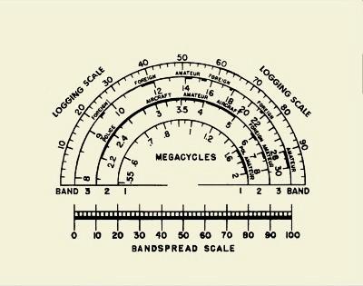 A replacement dial face I drew myself. If you want a larger image, drop me a line. By the way, I had to give the reproduced dial a slight yellow tint to match the old dial. Some
Antenna and Other Tips
These radios did not
come with a built in loop
antenna for the AM broadcast band as did almost every other AM radio of
its era. They were designed as a long range, more technical
general coverage
radio and as such they need an outside wire antenna of some kind.
The fact is, these radios are very "hot" if used with a wire
antenna of as little as 20 feet, but for great performance (especially
on the short wave bands), the best antennas are as long as you can make
them. When putting up an antenna, try to go vertical as
quickly
and as high as you can before going horizontal to minimize noise pick
up. When working at heights, please be careful. Try
to keep
the antenna away from noisy devices like motors and especially
fluorescent lights. If you have pieces of metal that rub
together
in the wind, try to clamp them down otherwise they will generate noise.You will notice on the back of your radio there are three screw lugs for the antenna system. When using an untuned long wire antenna, only the A1 lug should be used and that little jumper tab should connect A2 to the GND lug. The A2 lug should only be used with a tuned and balanced antenna system that is beyond the scope of most users. I would suggest that you not try to connect the GND or the A2 lugs to an actual ground as you may introduce some serious noise and hum that way. Anyway, the wonderful thing about these old radios is the opportunity to experiment around and find out what works best for you with what you have. Here is a nice tip from my EC-1b page: By the way, one really great way to find broadcast stations on the shortwave bands is to turn on the BFO and listen for loud "whistles" as you tune up and down the dial with the main tuning control. When you hear a whistle, tune as close to "zero beat" as possible and then turn off the BFO. Trim up the signal with the bandspread control and you have a nicely tuned in shortwave station to listen to. For me, this is probably the most useful thing a BFO does. Some
Final Words Regarding my EC-1 Today
This radio uses
variable capacitors for
its
bandspread and this alone
makes it somewhat superior
to my later EC-1b. This is my favorite radio for listening to
shortwave broadcasts because it is so quick and easy to tune through
the bands and see what band is active. I have the radio
placed
next to my Personal Computer for convenience so that when I get tired
of playing on the Internet, I just snap on the EC-1 and see if anything
is happening on KGO San Francisco on AM or anything on the short wave
bands. With a "real" BFO connected the way I have it, I can
listen
to AM, Single Side Band and Morse Code and it sounds fine regardless of
which kind of signal I'm listening to. By the way, these
radios only draw 30 watts, so they don't get hot and they don't waste a
lot of electricity.Have fun, I know you will. Recent addition: Just recently I was away from home for about a week on a remote ranch so I played Corporal Hogarth and brought my EC-1 with me. It was just the right size to toss in the back of my pickup truck along with my food and other gear. Once there, I strung a wire out to a tree and tuned in to the short wave bands at night. It really was fun having this old radio with me and I'm very glad I brought it along. I was all by my self out there and it was good company, but I am very sad to report that it failed to attract any pretty young women. I've been thinking of writing to Hallicrafters about that. THE END
Having
arrived this far,
obviously you have a superior attention span and reading ability that
far exceeds that of the
majority of web users. I highly value the opinion of people such as yourself, so I ask you to briefly tell me: Did
you enjoy this article
or were you disappointed?
If you have any detailed comments, questions, complaints or suggestions, I would be grateful if you would please E-mail me directly If you like my web page, tell your friends, if you don't like my web page, tell me If you enjoyed this article about my EC-1 and want to read more regarding this line of radios, perhaps you'd like to read about  Captain Allan Hancock's EC-1b Radio or maybe you would like to read about the line of Hallicrafters radios that replaced the EC-1s  My S-38b radio or maybe you'd like to read about the popular radio that heralded the end of the Hallicrafters general coverage receivers 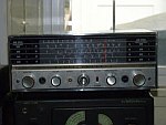 My S-120 Radio I have written a little essay you might like that explains some of the principles behind 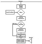 How The Armstrong Superheterodyne Radio Works There are a lot of other stories of my antique tube type radios on this website  Please select another antique radio article |