|
The
Hallicrafters S-38b Radio Project
Or How I finally put the parts back together after lying in a drawer for 40 years. A comprehensive story containing historical, educational, technical and biographical elements & opinions by John Fuhring 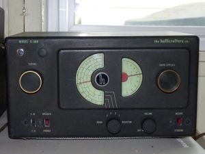 A Foreword to my S-38b Radio Story
The following
story is an account of how I took a completely disassembled S-38b
Hallicrafters receiver and built it back up from scratch.
Since I
rebuilt the radio as if it was a kit and not simply as a
restoration of an existing radio, this story is somewhat more
specialized than what many people expect. In addition, it is
written in a casual style with historical and personal elements that
make it more long and rambling than something that is simply a
technical article. With this regard, you might want to read
through the whole thing or you might want to skip around to the parts
that interests you.
My radio now contains several safety and electronic improvements and innovations that weren't part of the S-38b's original design and therefore you could discover within this story some ideas you might like to incorporate in your own radio. Personally, I think the story of my radio is extremely entertaining and very instructive, filled with some really great (dare I say, fantastic) ideas that everybody who loves old radios are just dying to read, but that is just my opinion and as of this moment, I haven't heard from that many people who agree with me. In fact, I haven't heard from anybody who agrees with me. Actually, most people think the story is stupid and boring, but that's just their opinion. Anyway, here's the story. Skip the parts you don't think applies to you and your radio, but please heed the warnings. A Short description and History of the S-38 Line of Hallicrafters Radios
The S-38
radios were the
successors to the Hallicrafters EC-1 line of radios and my
particular one was made sometime around 1950. In its day, it
was
considered a very stylish radio and to get just the right look,
Hallicrafters
hired one of the greatest artist of the Art Deco movement,
Raymond Loewy. I might add that Mr. Loewy earned the
Croix
de guerre in the Great War, but after it ended, he took ship and arrived
in the US still wearing his French Army uniform and almost penniless.
His great talent enabled him to go on to become perhaps the
greatest designer of the Art Deco movement and many of his designs are
highly collectible today.
Over the years, the S-38s came in several models with ascending letter suffixes (a-e). The original S-38 had no suffix and it was manufactured in the late 1940s. The S-38e was the last of the line manufactured sometime in the late 1950s and just before the S-120 line came out. This last model, the S-38e, has a slide rule dial and the same miniature tubes as the S-120, but has a case more similar to the older S-38 radios. All these radios perform equally well and they are all equally "hot" for such simple single conversion radios. Only the original S-38 has a "real" (vacuum tube) BFO, all the rest have an extremely crappy "IF oscillation" BFO that is all but useless for CW and completely useless for demodulating SSB voice broadcasts. Why Hallicrafters did this, starting with the S-38a model, I can only guess that it was a misguided cost cutting measure that really short-changed their customers. If you will read down further, you will see that something rather simple can be done to install a "real" BFO that actually works (and works very well indeed) in the later S-38 models. These S38s were made during a time in our country's history immediately after the Second World War and, in the days before CNN the 24/7 news stations and they were bought by curious minded people who wanted to keep informed with regard to world happenings and who were excited to hear voices from far away. They filled an important need many people felt for international news during this dangerous period in the world's history and because of that and the recreation they provided, they sold well and a lot of them were produced. For many people living today, these radios are a link to an important historical period in world and our country's history, but for others, they are a cherished and nostalgic link to their youth or to a well-loved parent or grand parent who had one. These radios aren't particularly difficult to repair (they could hardly be easier) and replacement parts are cheap and readily available, so if you have one of these radios and it doesn't work anymore, go ahead and fix it or get it fixed up by somebody who knows how. BUT BEFORE YOU DO ANYTHING, and if your radio is an S-38, an S-38a or an S-38b, please read and heed my safety essay before beginning any work on it or even plug it in. Simply touching the exposed chassis of one of the early model S-38 radios will give you a dangerous (and painful) shock and shocks from 60 Hz, 120VAC can kill a guy. The 38, 38a and 38b radios belong to the notorious "All American Five" (AA5) type of radios that were designed to operate without a transformer or an isolated chassis and so, like the others of this type, they have what is known as a "hot chassis" that can electrocute you if you touch it. In the following story, I'll tell you how I learned all about the shock hazards of AA5 type radios. Please note that if you have a S-38c, d or e model, yours has what I call an "isolated return bus" which means the chassis is "floating" and your radio is not a shock hazard.  AN IMPORTANT SAFETY MESSAGE YOU
NEED TO READ
BEFORE CONTINUING,
PLEASE READ MY SAFETY WARNING REGARDING THE EC-1 AND S38 MODEL RADIOS.
THESE RADIOS, IF UNMODIFIED FOR SAFETY, PRESENT A DEADLY
SHOCK
HAZARD AND SHOULD NOT BE USED OR PLUGGED IN UNTIL REWIRED.How I got my S-38b Radio
Sometime
around 1965, an old guy I happened to meet one day gave me his old
S-38b Hallicrafters
radio. It was basically just a piece of nonfunctional junk,
but
he thought I'd like to have it and and get it working again.
In those days, schematics for these radios were rare as hen's
teeth and, of course, I didn't have one. The layout of the
radio
looked pretty simple, so I thought I could trace out
any problems without a schematic. Perhaps I wouldn't have
been
smart enough to notice it, but a schematic would have shown how
dangerous the the radio is when it is plugged in and the chassis is
exposed.
I had a lot of experience working on old (1930's era) radios since my high school days, but they all had transformers and because they were isolated from the AC mains, they were intrinsically safe radios. My experience with these older radios led me to believe that a radio's chassis is the safest part of a radio. I didn't realize that these old Hallicrafters radios had what is called a "hot chassis" and that an ignorant or careless guy could get a terrible shock simply by touching any part of the chassis. Normally the owner of these (and other "All American Five") radios were prevented from touching the chassis by the insulated case and the back panel of the radio, but to work on the radio and find out what is wrong with it, the dangerously "hot" chassis must be exposed. Yes, I was ignorant of what a "hot chassis" was, but not for long. Soon I was to (painfully) to learn all about how bad they are. A
Shocking Development
My troubleshooting the old radio began
by plugging
it in so I could test for voltages. I had never heard of a
"hot chassis radio"
and so I was unaware of my danger. The moment I touched the
chassis of
the radio, I received a very severe
and
painful
shock that made a life-long impression on me. Actually, it
made
more than a simple impression, that bad shock
scared the bejezzus out of me and made me very afraid of the
radio. I was, ah ... shocked into believing that this radio
was
poorly and dangerously designed
and I immediately formed an opinion that a
radio designed
this way could not possibly be very good for listening to short wave.
I decided to gut the radio and rebuild it to a new
design using
safe, low voltage transistor devices.With these thoughts in mind and without thinking ahead, I ripped the radio apart. I removed everything including all the tube sockets, all the resistors, all the capacitors and all the wiring. I did not remove the variable (tuning) capacitors, the band selector switch and the two sets of tuning coils because I hoped to use them as part of a new transistorized radio. All the old radio parts I put in a shoe box and I planned to throw them all away as useless junk, but something stopped me. I have always hated to just throw stuff out (lord knows!), so instead of putting it in the trash, I put the shoe box in a unused drawer in an unused chest of drawers in a back storeroom of my parents' house. Once I had a stripped out chassis, I began to think about how to design the new radio, but then I realized that I had no idea how the tuning coils were arranged or how the band selector switch was wired up since I had no schematic. There was no Internet in those days and I had no access to a schematic. I was checkmated. 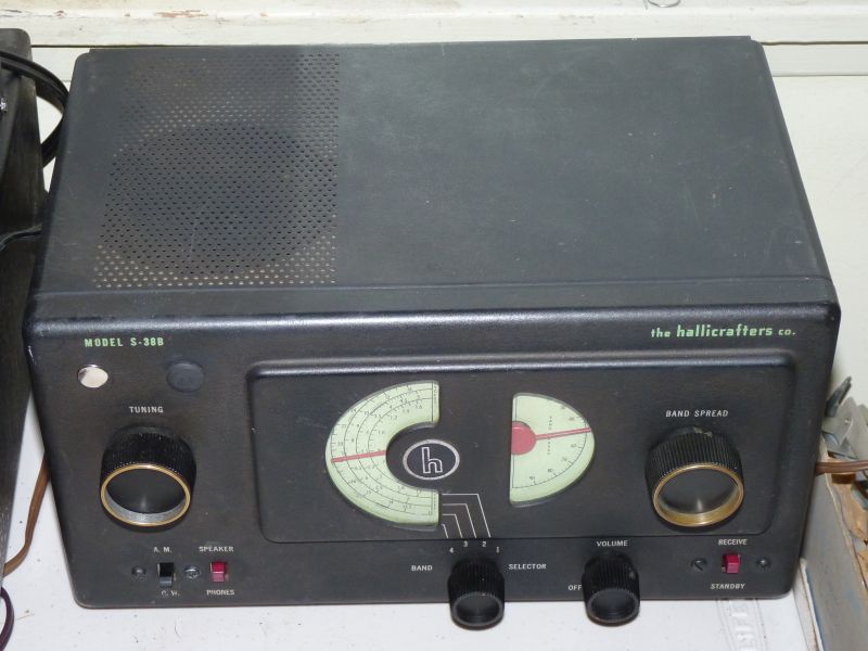 With the
radio all
redesigned and reassembled inside this case and with all the original
knobs found and in place, here's what my old Hallicrafters S-38b looks
like today.
Since I was stumped without a schematic and having lots of other projects to work on, I simply placed the radio's case with its stripped chassis on top of the same unused chest of drawers that contained the shoe box of old tubes, sockets and other parts. There the radio and its parts sat forgotten for 45 years while many dramatic things in my life and many important things in the world came and went. Finding
The Parts and Building The Old Radio up From Scratch
Recently, while cleaning out a back
room of the
house that I bought from my late parent's estate, I came across the
radio still
sitting on top of the old chest of drawers. When I saw it
sitting
there I had this feeling that this was a project that had been too long
neglected and
that I should do something about it or throw it out. Well, I
don't throw neat old stuff out, so
I considered
transistorizing the radio as I had once planned.
Before I started
drawing up plans, I had a
talk with a radio
designer who's opinion I respect. He suggested that
it would be better if I simply restored the radio back to the original
vacuum tube design.
The more I thought about it, the better the
advice
seemed to me (since I love tubes anyway), so I decided that I would
rebuild the radio along the same lines as the original, but this time I
would really do it right and use every engineering overkill that I had
learned in the 45 years since I got shocked so badly by this
radio.I looked at the bare chassis with all its missing tube sockets & internal parts and at first I was taken aback by the complexity of the task. I wondered where I'd get all the obsolete parts I'd need to rebuild the old radio and if I could really do it. Suddenly, to my surprise, ancient memories came flooding back and I recalled exactly where I had stored the parts in that shoe box as if it had been only yesterday. I went to a drawer in that old chest that hadn't been opened in 45 years and sure enough, in that very shoe box, there were all the parts just where I had put them so long ago. I went to the Internet and downloaded a schematic diagram. I took a long, hard look at the schematic and at the bare chassis and all the parts in the shoe box. The more I looked, the more I could see that this would be a relatively easy project. Suddenly I had no qualms about starting this project because, over the years, I have designed and built much more complicated radios than this one and the schematic made it look so charmingly simple. Yes, I thought that it should be pretty darn easy to rebuild this thing and you know what (??) It was easy, even to adding all the safety features and the "real" BFO that makes it the great little radio it is today. With the help of the schematic, I selected the parts I could reuse from the shoe box and made a list of parts I'd need to buy at my Electronics Parts Supermart here in town. It turned out that I only needed about four electrolytic capacitors, a dozen or so disk ceramic capacitors, a spool of 22 ga. insulated hookup wire, a toroid oscillator core, a common FET and a trimmer capacitor for my new BFO. That's it. That's all I needed to buy in order to restore the radio. The total bill for all the new parts came to less than $30. Beginning
the project and hearing the radio play for the first time in 50 years
I began by cleaning all the solder off
of all the
tube sockets and terminal strips so I could begin at the beginning.
I then placed all the
tube sockets in their holes and bolted them down rather than try to
rivet
them in as had been done at the factory. I mounted all the
terminal strips and then, with the help of the schematic diagram, I
began to wire it all up. As I have written elsewhere, a schematic diagram is correct electronically, but is not necessarily the way a radio is actually wired up. I have no idea if I followed the factory way of wiring or not, but electrically it doesn't matter as long as everything is connected correctly. As I worked, I took it one tube socket at a time and soldered in all the parts for that tube, then I moved to the next tube. In a surprisingly short amount of time (a single evening) I had the radio completely rebuilt and ready to plug in. I know this sounds very nerdy, but it was actually fun, very much like solving a puzzle, putting this thing back together. The next day, after I had wired it up and all the parts were in, I again took the schematic and with a red pencil, went through each and every wire and component. As I confirmed each wire and each part, one at a time, I'd redline it. To my surprise, I found a couple of instances where I had left something out, so I'd stop and put the missing wire or part in then redline it. Finally, the radio and the schematic matched perfectly. If my career in aerospace has taught me anything, it is the vital importance of through inspection and quality control. Craftsmanship is important too, but all work should be inspected before a circuit is energized. The result of all that careful checking was that the radio came to life and began to receive stations loudly and clearly within a few seconds after turning it on for the first time (the normal warm up time of the tubes) . Nothing smoked, nothing hummed, but I could hear the normal "white noise" an AM radio makes when you turn up the volume control. I turned the tuning knob and a station about 15 miles from here came in loud and clear with good clean audio. I didn't need to do any troubleshooting to find out why something wasn't working, no, everything worked perfectly the first time and you know, that is a wonderful feeling. The
Importance of A
Good and Usable Schematic Diagram
Another important lesson I learned in
my career as
a
'Dilbert' kind of
electrical engineer is the supreme value of a good schematic diagram.
Back
45 years ago when I first began to work on this radio, a schematic was
impossible to find, but now, thanks the astounding development of the
Internet, finding a schematic for this (and just about any radio ever
made) is easy. The only problem with schematics captured over
the
Internet is that they are generally hard to read, so to have something
good to work with, I began
the task of completely redrawing the schematic. To tell the
truth, I
have put more hours in creating really good schematics for this radio
than I have
spent actually working on the radio, but it was fun and time well spent.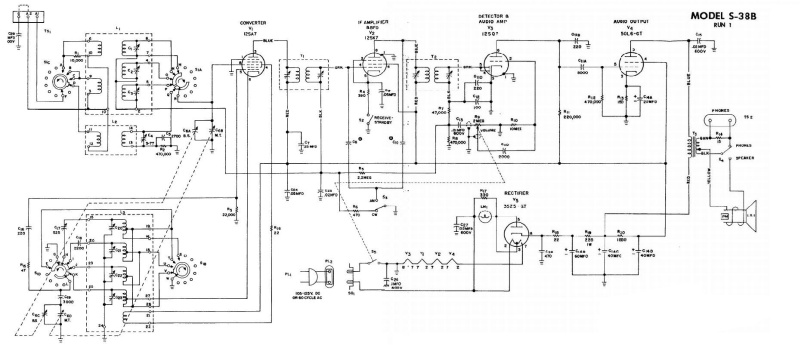
Ground
rules before beginning this project
As I mentioned earlier, I resolved to
rebuild this
radio as a vacuum tube set, but I WAS NOT going to restore the
radio to precisely its
original design. No, this was not going to happen
because I
still remembered
the terrible shock I had received many years earlier. I said
it
made a real impression on me and, believe me, it did. I
looked
over the schematic and with its help, I devised ways by which I could
make it shockproof and ultra safe by incorporating every ridiculously
over-engineered
safety feature
(that an obsessive engineer who had had the crap shocked out of him as
a
youngster) could think of. The only engineering overkill I
wasn't
going to do was to install an isolated power
transformer since one shouldn't be necessary with all the other safety
features I was planning. There were TWO things I especially wanted to accomplish rebuilding this radio: (1) the radio had to be shockproof. I made it so by creating a return bus electrically isolated from the chassis and connected to AC Neutral through a polarize the AC plug. I connected the outside case to AC ground for extra safety. The truth is, it really isn't necessary to create a isolated return bus connected to AC Neutral through a polarized plug as I did. It works just as well and is just as safe if you wire the chassis to AC Neutral and leave the other wiring alone. It is a lot simpler that way and you can get the restoration job done a lot quicker. Since I had to completely rebuild the radio from scratch and install new wires in it anyway, it wasn't that much trouble to create the isolated bus, but for my EC-1 and EC-1b, I did not do that and they are perfectly safe too. Please read my safety article to see how these radios can be made safe to use without using an isolation transformer. (2) The radio had to have a "real" BFO rather than its very poor IF feedback BFO it was designed for. The fact is, when I first rebuilt this radio, I built it according the the original design and I used it that way until I became disgusted with the way it worked. As an experiment, I built a tiny BFO module using a FET and a little coil I wound myself. I took power from the voltage available at the cathode of the audio output tube. Let me tell you, I was just amazed at and so pleased by how well this BFO worked so I removed the feedback gimmick capacitors and put in the little FET BFO permanently. To put it mildly, this little change has vastly improved the overall performance of my radio and I sincerely urge you to add one of these to your radio too. If you will stick around, I will give details on how I built and installed my BFO shortly, but first let me finish telling about rebuilding the main part of the radio. Building
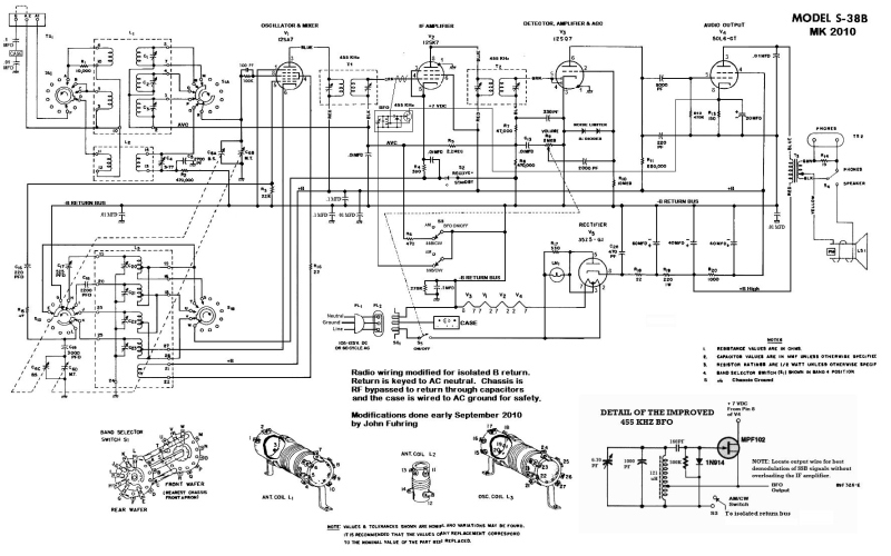
an Ultra Safe Isolated Return Bus for my Radio
The following is a redrawn schematic of the S-38b showing the isolated
return bus I created for my radio:
I am a little
proud of myself for coming up with the idea of an isolated return bus
and it does make this radio very safe. I'll admit that with
all I
have learned about making "hot chassis" radios safe, I would not have
created this isolated return bus if I had this project to do over
again. Having
said that, I do want to tell you about the isolated return bus because
the creation of this bus is part of the story of my S-38b radio.
So, like it or not, here it is: (you can skip this
part if
you want to)
What I am calling an isolated return bus is simply
interconnected wires that provide a power supply ground or return that
is isolated from the
chassis in terms of your house's 120 volt, 60 cycle mains current.
Each place in the chassis where there had been a connection
of a
component to the
chassis (with the
exception of the tuning and trimming capacitors) I lifted its wire and
connected it to this bus. I then "RF coupled" this bus to the
ground of the chassis by using capacitors. It is
just as simple as that. By doing so, I could allow the
chassis to
"float" with respect to the AC power and thus, not being connected to
AC in any way, the radio is ultra
safe.
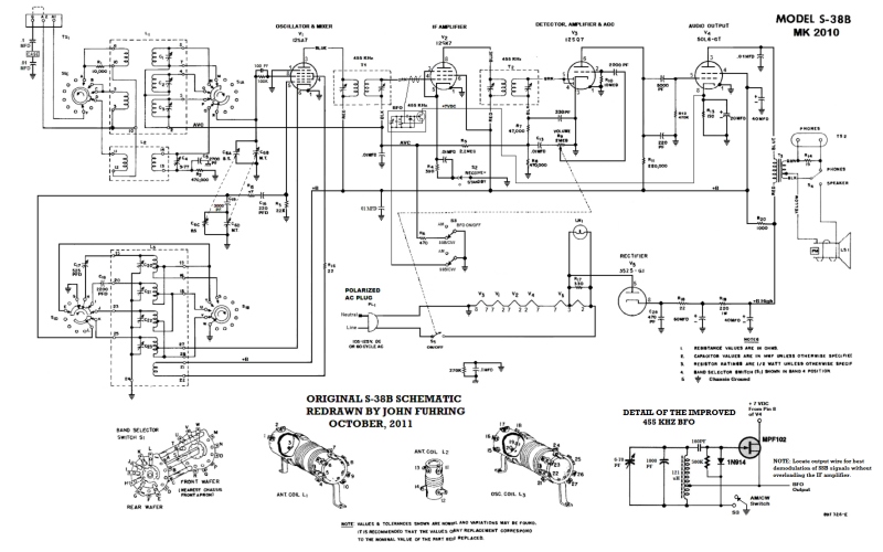
OK, that's all I'll say about my radio's isolated return bus. Restoring
and improving
an S-38b without creating an isolated return bus.
Please note that the schematic diagram
below (and
one I think you should work to) also shows the really great little
BFO I
installed in my own S-38b.
The truth is,
creating a isolated return bus is not
necessary as these radios perform just as well if you simply connect
the chassis to the Neutral side of the AC line. Please read my essay on how to make
these radios
safe. I have restored
two EC-1 radios without a return bus and they are just as electrically
quiet and just as safe (after I modified their power connections).
I suggest you not create more work for yourself and just
restore
your radio as shown in the schematic diagram shown below. If
you
want a larger version of the schematic, just E-mail me.
 The conventional
S-38b schematic
using the chassis for signal return.
If I had it to do over, I would have built my own radio to this diagram. If you would like a larger version of this diagram, send me an E-mail. What
parts must be replaced and what parts should be left alone
The only parts I needed to replace in
my radio were
those
terrible paper/wax capacitors and the electrolytic
capacitors. I didn't replace anything else because I didn't
have
to. It has been
my experience over the years that silver
mica capacitors never go bad nor do most resistors. This
radio
uses five silver mica capacitors and none of them are very critical, so
even if they are a bit out of specifications, the overall performance
of the radio isn't effected. Unless a resistor has
been overheated, it is my opinion that it should be left alone and not
replaced and you know, except for obviously burned up ones, I've never
replaced a resistor in any of my old radios. The fact is,
thanks
to vacuum tube technology, none of the circuits are at all critical and
none of them require high precision components. All the tuned
circuits can be adjusted if the components drift a bit over the years,
but, amazing as it seems, I've found these radios need little
or
no adjustment. My suggestion is just this: if it ain't a
paper/wax or
electrolytic capacitor and if it ain't burnt or falling apart or
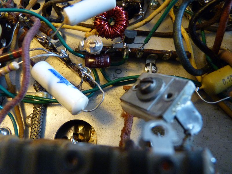
otherwise malfunctioning, leave it in there.I have no idea what former owners did to this radio to keep it working over the years, but evidently nobody ever touched the adjustments to any of the tuned circuits. In fact, I was somewhat surprised that none of the RF circuits or the IF transformer circuits needed any aligning. After all these years and after all the tinkering, people must have done, the radio was essentially still in tune. I do have all the equipment to accurately realign a radio such as this, so I tweaked all the tuned circuits, but it really wasn't necessary. If your radio sounds good with plenty of volume, I wouldn't touch it. The photos below show the bottom of the chassis as it looks today. If you look closely you can see a lot of the old cloth covered wired that I reused (they were in good condition) and it also shows the many new wires (mostly green colored) that I installed to create the isolated return bus. You will also see a lot of new parts I put in there to replace the old paper/wax capacitors. Note how tiny the electrolytic filter capacitors are using today's technology. They take up so little room that you hardly recognize them as filter capacitors. Near the upper-center of this view is the FET BFO that I built for this radio and the second photo shows a closeup of the circuit. The insides of my S-38b receiver showing all the new and old parts and the new wiring. The
Importance of a Good BFO
The EC-1 series and the original S-38
model all
have a
"real"
BFO that uses a triode tube for the oscillator, but
for some reason, starting with the S38-A model and continuing through
even to the S-120 model, all the other radios came with a cheap and
lousy IF self-oscillation design. The way the BFO works in
these
later radio is for the "gimmick" capacitors (actually just wires
twisted
together) to couple the IF tube's output to its input. This
was
Hallicrafters
extremely poor excuse for a BFO. The original BFO is all but
useless
at demodulating single side band voice (SSB) and even listening to
Morse
Code (CW) transmissions is extremely difficult because this poor excuse
for a BFO is so unstable. I can only
assume that the Hallicrafters marketing people felt that most people
didn't use the
BFO anyway, so having a cheap, useless self-oscillating IF was just
barely good
enough to give them the right to claim that their radios "comes with a
BFO" without actually lying.
Not exactly false advertising, but getting very close.
Yes,
these Hallicrafters radios came with a BFO, but don't expect it to do
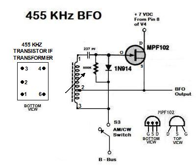
anything useful.If you still have a original BFO and you hate the way it works, don't despair, there is a cheap and easy fix for this that works wonderfully. If you look closely at the schematic you will notice that the "real" BFO I put in my radio uses a FET circuit that is run by the +6 VDC taken from the audio amplifier (V4) tube's cathode bias resistor. The BFO module draws only microamps of current, so it doesn't effect the operation of V4 in the slightest. To build the module, I wound the oscillator coil on a little toroidal form for just the right frequency of 455 KC (or Hz as we say today). This simple little FET BFO works much, much, much better than the original design and, to say the very least, I am very pleased with my little modification and how great it works.
The FET
transistor is that black semi-cylindrical thing, the Hartley oscillator
coil is the red
donut shaped thing, the purple bean shaped thing is the 237 pF coupling
capacitor (100 pf will work just fine) and the frequency is tuned to
455 KCs with the
screwdriver slot thing.
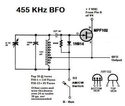
The only thing
that
is in the least critical about the FET BFO (besides tuning it to 455
KC) is where to place the BFO output wire.
I found that laying the end of the wire next to the wire that
goes to the grid (pin 4) of the IF amplifier (the 12SK7 tube) is all
that is necessary for proper coupling so that you get good mixing.
If you place the wire too close and couple the signal too
strongly, you will "swamp" out the IF
amplifier, but if too loosely coupled, you won't get good SSB
demodulation on strong signals. If your off the air signals
appear weak and the normal static goes quiet when you turn on the BFO,
it's because the IF tube is being
"swamped" and you need to move the output wire further from pin 4.
Actually, turning on the BFO will tend to make the normal
static
(white noise) somewhat louder when the BFO is working properly. An alternative FET BFO design suggested by a reader
A Triode Tube Alternative
Just
today (Oct.
3, 2012) somebody asked me how frequency stable the little FET
BFO
really is and how useful it is at demodulating SSB considering the
normal frequency drift of the Local Oscillator. First, the
BFO's
frequency is very stable amounting to only a few Hz a minute, so it
really isn't a consideration. Secondly, in my S-38b, in my
S-120
and in my Fairbanks Morse radios, this little circuit works
surprisingly well at demodulating SSB, but certainly not as well as a
ham band radio with no frequency drift. The truth is, you,
the
operator, must keep "tweaking" the fine tuning to keep the voices
sounding perfectly natural. I find it quite easy to do
because I
like fiddling with things while I'm listening anyway.
However, if
you are expecting to be able to walk away from the radio while still
listening to a conversation, you will be disappointed. Of
course,
even with a rock solid LO, there may still be annoying differences
between the different sides of any conversation, so natural sounding
voices are always a problem when listening to SSB.The same person asked me if they couldn't use a real vacuum tube rather than a modern FET. Sure, you could install a 12SQ7 and change the 50L6 audio output tube to a 35L6 then wire the 12SQ7 into the heater string. You could use the triode section of the 12DQ7 in the place of the FET and it would work OK. This is exactly how the EC-1b does it (see my EC-1b story). Now, having said that, you can not add another tube in the string without recalculating the total voltage drop and your new tube's filament must draw the same current as the other tubes do. What I mean is this: all the tubes in the S-38b draw 0.15 amps of current so your new tube must draw this too -- you can not use a tube that draws more than this. If it draws more current, the other tubes will light, but the new tube won't. Six volt tubes generally draw 0.30 amps, but each tube in the S-38b only draws 0.15 amps (as mentioned), so a 6 volt tube won't work. Speaking of voltages, the total voltage drop of the entire string must be somewhere close to 120 volts, so adding a 12 volt tube in the string will require 132 volts. Now where are you going to get that? Yes, the heaters of most tubes will operate at a lower voltage, but your radio's performance might suffer and an otherwise good (but slightly "soft") tube might appear to fail prematurely. To get the voltage right, (as mentioned) you will have to change the audio tube to one of lower voltage, but the same current (you need to change to a 35L6 just as the EC-1b uses). Perhaps an alternative to changing the 50L6 tube and using a 12SQ7 tube would be to use a 1H5 tube with a 15 ohm 1/2 watt resistor in parallel with the heater circuit. You'd only be loosing 1.5 volts and that's not enough to affect your radio's performance. If you do this, I strongly suggest you place the tube's filament at the chassis end of the heater string because if you short anything to chassis, you could blow one or more of the other tubes and you might have some dangerous AC voltages present since the heater is the cathode and besides it will make bypassing the cathode to chassis ground much simpler. Now, my question in return is why in the name of goodness would you go to all the trouble of punching a hole in your chassis, locating and buying one or two new tubes and a tube socket? I think that's nuts, just plain nuts - don't do it. The FET module works as well or better than a triode and it can be built for a tiny fraction of the cost of one or two new tubes and a socket. The work involved in installing a FET module is a tiny fraction of the work involved in installing a tube. You will still have to wind a oscillator coil and mount a tuning cap, so you won't be saving any parts or labor by using a tube. For all these reasons, radically modifying your radio for a tube BFO is (to put it very mildly) not recommended. Do yourself a favor and build the FET module if you want a "real" BFO. "Oh, but a FET is too modern" you say. First, nobody is going to know and besides, if you are obsessed with absolute authenticity, you shouldn't be punching holes and mounting any novel parts in your chassis anyway. If you somehow "need" to have your radio "correct for the period," you should just leave your crappy BFO in there as it was designed by the factory and resign yourself to crappy BFO operation. If you have any questions regarding any of this, drop me a line. I'll be glad to harangue you at great length over this if you want me to. Here is a useful BFO tip from my
EC-1b page:
By the way, one really great way to find
broadcast
stations on the
shortwave bands is to turn on the BFO and listen for loud
"whistles" as you tune up and down the dial with the main tuning
control. When you hear a whistle, tune as close to "zero
beat" as
possible and then turn off the BFO. Trim up the signal with
the
bandspread control and you have a nicely tuned in shortwave station to
listen to. For me, this is probably the most useful thing a
BFO does.Some
Antenna and Other Tips
These radios did not come with a built
in loop
antenna for the AM broadcast band as did almost every other AM radio of
its era. They were designed as a long range, more technical
general coverage
radio and as such they need an outside wire antenna of some kind.
The fact is, these radios are very "hot" if used with a wire
antenna of as little as 20 feet, but for great performance (especially
on the short wave bands), the best antennas are as long as you can make
them. When putting up an antenna, try to go vertical as
quickly
and as high as you can before going horizontal to minimize noise pick
up. When working at heights, please be careful. Try
to keep
the antenna away from noisy devices like motors and especially
fluorescent lights. If you have pieces of metal that rub
together
in the wind, try to clamp them down otherwise they will generate noise.You will notice on the back of your radio there are three screw lugs for the antenna system. When using an untuned long wire antenna, only the A1 lug should be used and that little jumper tab should connect A2 to the GND lug. The A2 lug should only be used with a tuned and balanced antenna system that is beyond the scope of most users. I would suggest that you not try to connect the GND or the A2 lugs to an actual ground as you may introduce some serious noise and hum that way. Anyway, the wonderful thing about these old radios is the opportunity to experiment around and find out what works best for you with what you have. Final
Thoughts on my S-38b Radio
The S-38 radios were not the most
sophisticated
radio Hallicrafters ever made and they were considered unsuitable for
ham
radio
operation, but as a general purpose short wave listening radio, they
enjoyed a
very good reputation and went on to be the most popular line of radios
Hallicrafters ever made. My radio uses the same or similar
tubes
as the earlier
EC-1 radios and it is just as "hot" as they are at bringing in weak
signals. The extra band and its very smooth tuning
makes it
a somewhat nicer radio to play around with than my EC-1s. Now
that my S-38b is restored, it is
as safe as a radio can be and that is a nice feeling. With my
"real" BFO installed, my radio works very well for listening to SSB, CW
and AM. Somehow, the weight of the
radio and the ease with which the tuning knobs turn make the radio feel
extremely "solid" and with a feeling of quality that exceeds my later
S-120. When short wave band conditions are decent, this radio
works well enough to allow me to
listen to the hams chat on SSB or CW.I wish you the best luck and enjoyment in your own S-38 project. The End Having
arrived this far,
obviously you have a superior attention span and reading ability that
far exceeds that of the
majority of web users. I highly value the opinion of people such as yourself, so I ask you to briefly tell me: Did
you enjoy this article
or were you disappointed?
If you have any detailed comments, questions, complaints or suggestions, I would be grateful if you would please E-mail me directly If you like my web page, tell your friends, if you don't like my web page, tell me. If you enjoyed this article about my S-38b and want to read more regarding an earlier radio, perhaps you'd like to read about 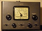 My World War Two era EC-1 If you would like to read about how I restored a radio salvaged from a trash pile 50 years ago, perhaps you'd like to read about 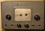 The EC-1b Radio from Captain Allan Hancock's Flying Field or maybe you'd like to read about the very popular radio that heralded the sad end of the Hallicrafters company  My S-120 Radio I have written a little essay you might like that explains some of the principles behind  How The Armstrong Superheterodyne Radio Works I have a lot of other stories about my radios and early radio technology you might be interested in  My vintage radio stories and articles As a last resort, you can Return to my Home Page and look for something interesting |