RADIO TECHNOLOGY
IN COMMON USE CIRCA 1914 An essay just for fun by John Fuhring  A French military crystal receiver of 1914-1918. British, German and American military radios were almost identical in design and operation. These receivers worked well with the spark transmitters also in use at the time. The schematic of the very similar American WW1 radio is shown below. Introduction
In the earliest days of radio communication, clear
up into
the 1920s, spark gap transmitters were used to generate
powerful
waves that
could send their signals for hundreds of miles. At first
though, radio
receivers used detectors that were
extremely "deaf" and so the distances these waves could be detected
was extremely limited. The first practical radio detector was
the
coherer and for more information on the coherer I would like to
invite you to read my coherer essay
found elsewhere on my website. There is also a link at the
end of this essay.Recognizing the limits of the coherer, scientists at the Marconi Laboratory developed a moving iron wire detector (the famous "Maggie") that was hundreds of times more sensitive than even the most advanced coherer detector. Of course the Maggie was a "professional" detector that was very expensive and used only by the Marconi company. Around 1910 it was discovered that simple and very, very cheap crystal detectors were actually superior to the Maggie when set to a good "hot spot" on the crystal. This development spelled the doom of the coherer detector, but opened the world of radio to thousands of amateur radio operators. Out of the ranks of these early amateurs came nearly all of the famous names in early radio technology and the future radio operators who tied the world together in commercial and military radio networks. Even to this day the lowly crystal radio is, for many children, their first exciting introduction into the magic that can be found in the world of science. By 1914, the target date of this essay, there were several kinds of detectors already in use, including Armstrong's marvelous regenerative detector, but perhaps the cheapest, most rugged and reliable and certainly the most popular detector of this era used a crystal diode. Only official Marconi equipped ships used the less sensitive Maggie magnetic detector or the excellent, but fragile and expensive Flemming Valve detector. Only dedicated amateurs, universities and certain US and British Navy ships used the fragile and expensive (but superior -- when it worked) gas filled Audion tube. In this essay I will describe only the crystal receiver because it was so popular and in universal use by ships at sea, the military, amateurs and commercial radio networks. Please note, many the principles I will describe apply to diode detectors (crystal and Fleming Valve), to the so called "grid leak detector" using an Audion tube and even (in many ways) to the Maggie detector. I will leave it to you to read about other detectors described in my coherer essay. To establish a complete radio communications station, a transmitter is needed and so I will follow the crystal receiver discussion with a discussion of a basic transmitter of the era. This essay will describe a rotary spark gap transmitter similar to the ones that were in common use from the beginning of radio all the way up into to the early 1920s. I realize that there were other kinds of transmitters by this time, including the Poulsen Continuous Arc and the Alexanderson Alternator, but the Alexanderson was huge and both it and the Poulsen were poorly suited for sending radiotelegraph signals that could be heard by the receivers in common use at the time. By far, the most popular kind of transmitter was the spark gap type, so I will leave a discussion of other types of transmitters to other websites. I would like to begin my essay with a discussion of the most common, but effective radio receiver in use at the time, a crystal diode radio receiver. Please note that many crystal receivers are much more complex than the one described and that was done to improve their performance in certain ways, but all have at their core, the technology I will present. The crystal
receiver
 Details of a basic, but usable crystal receiver A basic crystal
receiver consists of the following elements:
1. A long wire "Marconi" antenna. 2. A coil and condenser to "tune" the antenna to the resonant frequency. 3. A tank circuit consisting of a tunable coil and condenser. The coupling between these coils is variable. 4. A crystal "cat's whisker" detector such as shown above. 5. A set of sensitive headphones. 6. A good ground connection (to the hull of a ship or the sea is ideal). How a crystal receiver works 
Here
is a graphical representation of what's going on when a radio frequency
signal is detected (turned into sound):
Although a radio receiver with a crystal detector can be as basic as the one described, the crystal radios used by the world's military (such as the one shown above) and by ships at sea and by commercial installations and by many amateur radiomen were somewhat more complex, as I mentioned above.  A schematic diagram
of the American version of the French radio shown at the top of the
page.
The extra coil and other components were used to improve the performance of the receivers and to cut down on the interferrence caused by adjacent radio stations, but what has been presented here is the very same unamplified diode detector technology. A Basic Spark-Gap
Transmitter
Similar in design to the transmitter used by the RMS Titanic and the Mawson's expedition and countless other radio installations including military, commercial and amateur  This type of transmitter is capable of radiating several hundred watts of power Transmitters with really huge tank circuit condensers were capable of radiating thousands of watts. Spark gap transmitters are also
quite simple although not
nearly so much as crystal receivers.
A transmitter using a motor-generator for its power, such as shown in the schematic above, consisted of the following components: 1. A generator set consisting of a gasoline motor connected to a 240 volt AC dynamo. Of course, on land, the high voltage transformer could be connected to the AC power mains (as was done in the high power stations) instead of a motor-generator. On advanced designed ships of the era, such as the Titanic, shipboard electricity was available at 100 volts of DC power and so a motor-generator (a dynomotor) was used to generate the AC necessary for the transformer. Ships of that era generated 100 volts DC, used throughout the ship, because it was many times safer for the crew and passengers than AC power. 2. An ordinary telegraph key that is really just a very easy to operate momentary contact switch. Remember, this was the age of radio telegraph and before voice radio was practical. 3. A high voltage step-up transformer. The transformer actually consists of two coils, a primary consisting of just a few turns of thick wire that carries heavy current (several amps) that is interrupted by the telegraph key and a secondary coil consisting of very many turns of a thinner wire that produces a voltage of several thousand volts. 4. A choke coil to keep high voltage radio waves from entering and damaging the transformer. 5. A high voltage capacitor, also called a condenser in the old terminology. This condenser would usually be made of glass plates separating metal plates. The value of this condenser would be relatively huge in the order of 1 or more micro Farads. It would be rather huge in size too to stand the high voltage. The condenser forms one half of what is known as a "resonant tank circuit." 6. The other half of the resonant tank circuit is an adjustable tuning coil. While the coil might be physically large to stand the high voltages, the coil's inductance value is small, in the few micro henry range. By selecting different taps on the coil, the broadcast frequency of the radio may be changed from 100 kilocycles per second (KHz) to 1,200 kilocycles per second (KHz) and everything in between. Near the middle, at 500 KHz, was the international distress frequency and the top, 1,200 KHz, was the "shortwave" frequency. 1,600 KHz is about as high as a spark gap transmitter can go and still put out adequate power. The frequency that these transmitters put out was determined by the resonant frequency of the tank circuit and was, by no means, very stable in contrast to the later crystal and synthesized frequency continuous wave (CW) transmitters. 7. The key component that enable the tank circuit to oscillate is the spark gap. The spark gap, when it isn't discharging, allows the tank condenser to charge up to several thousands of volts and store many (sometimes hundreds of) watts of energy between discharges of the spark gap. More powerful and elaborate transmitters used a more complicated "synchronous rotary" type of spark gap. A multi-gap rotary allows multiple (around 10 instead of 2) discharges for every AC cycle thus greatly improving the efficiency and power output of the transmitter. Since there are many discharges for each AC cycle, the triangle waves are closer spaced and the pitch of the musical note is raised to about high C so that it is easier to hear. 8. The final component inside the transmitter is the antenna coil that is inductively coupled to the tank coil. This coil is adjustable and it allows the matching of the antenna to the tank circuit so that energy can be pulled out of it and radiated by the antenna. To help get a good match to the antenna, a "hot-wire" ammeter indicated when maximum antenna current was flowing. 9. No transmitter or receiver will work without some kind of antenna. Marconi and his scientists had earlier worked out some very clever and effective designs that got out the best signal for the wavelengths these radios operated at. At the 500 kHz distress frequency, a good performing 1/4 wave long wire antenna would have to be around 450 feet long. This length was impossibly long except at the largest ground stations and so the famous Marconi multi-wire top-loaded 'T' antenna was developed. When used with a tuner, it put out most of its energy horizontally which means that the radio wave followed the curvature of the earth and out for hundreds of miles and very little energy was wasted by going up into the sky.  The Marconi top-loaded 'T' antenna on the RMS Titanic. This antenna is typical of radio aerials of the time. Old pictures of ships and radio stations clearly show this kind of antenna as four or more parallel wires strung between horizontal masts and attached to the masts of the ship and feed wires going from these wires to the radio room. How a simple spark-gap
transmitter works
Ultimately, the power that is radiated into space by the transmitter comes from the energy produced by a generator or the electrical mains. When the telegraph key is closed (as when the operator wants to send a Morse Code dot or dash), a heavy current starts to flow in the primary windings of the transformer. That current starts to produce a large magnetic field in the iron core. The rapid build up of the magnetic field in the core induces a high voltage in the secondary coil. As the AC wave swings from positive to negative and back to positive, a similar, but very high voltage wave is produced in the secondary at the same frequency as the primary AC wave. This secondary voltage, despite its high voltage, is still a simple alternating current (AC) which means that the positive voltage builds up to a peak, descends to zero and then builds up to a negative peak and again descends to zero. Of course, it is doing it very fast at about 50-60 times per second which you can hear, but you can't count (without electronic devices). Anyway, as the voltage is building up (either positive or negative), the tank circuit condenser is charging up and across it there develops several thousands of volts. Stored in the condenser, at least briefly, is many watts (sometimes thousands of watts) of electrical energy. While the condenser is charging, the spark gap presents an open circuit and no current is allowed to flow to or from the tank coil. When the voltage rises to near its peak, the spark gap can't hold it back any longer and an electrical arc (a spark) jumps across the gap. The air between the gap ionizes and the resistance across the gap goes to a very low value. It is exactly like a high speed switch has closed at just the right moment. When the arc is struck and the resistance across the gap is now quite low, the tank coil is suddenly connected to the tank condenser and they start to exchange energy between themselves at their resonant frequency (100 KHz or more). This energy is coupled to the coil of the antenna tuner and from there it goes out the antenna as radiated energy in the form of radio waves. When the voltage on the opposite slope of the AC wave decreases below a certain point or if the gap is suddenly opened by being on a rotating disk, the electric arc across the spark gap is broken and the circuit between the condenser and the coil breaks. When the arc is broken (called "quenching"), the connection to the tank coil is open circuited and this allows for voltage to build up across the condenser once again for the next go-around. With a spark gap transmitter, it doesn't matter if the next voltage swing is positive or negative, a triangle wave will be produced in either case. A rotary spark gap will create any tone the operator wants to set it for. For example, if he wants a distinctive 600 Hz tone, he turns down the speed of the motor attached to the multiple rotating spark gaps, but if he wants something higher, he speeds up the motor. When the spark first occurs, a large pulse of energy, vibrating at the desired radio frequency, is produced, but then the energy immediately starts to decline forming a triangle wave as mentioned above. The train of triangle waves thus produced is at the frequency of a musical tone and so it is heard as a musical note by Fleming Valve detectors, crystal detectors, Audion detectors and by Maggie (magnetic) detectors (all in use at this period). All transmitters of this era had their own unique musical sound and so professional radiomen knew who was transmitting without even hearing their call signs and, what is more important, an experienced radioman could "pick out" by ear the transmitter he wanted to listen to from the mass of signals he'd hear in his headphones - yes, the human ear is that marvelous. The Titanic's synchronous rotary spark gap had a musical tone that was easily recognizable, so everybody knew that the distress messages they heard were authentic. A final word on
spark-gap transmitters
Spark
gap transmitters have a bunch of flaws. One of the biggest
flaw
is the fact that for really high power operation, the condenser must be
huge in terms of capacitance in order to store a big charge and the
voltages must also be huge which then requires the condenser be even
larger to stand those high voltages. Some of the very high
powered ground stations had condensers that occupied a large building.
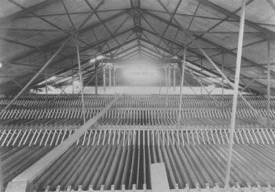 The Attic of the Cape Breton Transmitter Site's Condenser Building The condenser consisted of 288 sixty foot by twenty foot metal sheets that extended from the roof to near the floor Touching a charged component of one of these transmitters, even if the power is off, would result in instant death and so crowbar like grounding bars would be used to discharge the condenser when the transmitter was down for repairs. Because they needed such large value condensers to store large amounts of energy, these transmitter's tank circuits could resonate only at very low frequencys. Anything above 600 kilocycles (KHz) was considered "short wave" and therefore they were unable to take advantage of operating at higher frequencies (like 3,000 to 30,000 kilocycles) where ionospheric "skip" enables even low power transmitters to be heard hundreds to thousands of miles away. Another disadvantage of high power stations, not usually mentioned, is how loud and dangerous it was to be in the same room with the spark gap. With thousands of volts exposed and producing an extremely loud crackling noise, the spark gap was usually housed in a "silent room" that was anything but silent if you were in there while the transmitter was operating. The room had to be physically removed from the operating room and had to be extensively sound proofed or the noise would damage the hearing of the radio operators. Spark gap transmitters are called "dirty" because they spread their energy over such a large part of the radio spectrum. The useable energy they transmitted was actually just a small fraction of the huge amount of energy they put out, the rest was wasted in polluting the radio spectrum. This "dirtyness" touches on absolutely the most serious spark gap transmitter flaw and the one that doomed their use after 1920. Triangle waves put out a wide band of interference and as the world of radio communications became more and more crowded, these transmitters just couldn't be used any more. Finally, spark gap transmitters are highly unsatisfactory for voice and music broadcasts. There were flea power transmitters that had carbon microphones attached to them, but trying to talk over the triangle waves the radios produced was nearly impossible. Beyond this serious shortcoming, there was at the time, no powerful modulators that could superimpose voice on to the more powerful transmitters. That being said, in the early days from the 1890s through the early 1920s, they performed marvelously in two areas: They produced radio waves with so much power that the early detectors, as "deaf" as they were, could hear them hundreds of miles away. That and the fact that the triangle waves were the only kind of radio waves that the early radio detectors could hear. Because triangle waves are a form of "amplitude modulation," the dots and dashes of the Morse Code could be heard as musical notes and not simply as nearly inaudible hissing sounds. The use of Beat Frequency Oscillators (BFOs) were only in the experimental stage and didn't come into practical use until after 1920, so the more powerful and electrically "clean" Continuous Wave (CW) transmitters, such as we use today and operating at much higher frequencies, just would not have worked. As with Edwin Armstrong's marvelous inventions that came later, we owe a lot to spark gap transmitters for ... ah ... jolting or ... ah... galvanizing .. the Age of Radio off to a good start and providing just the .. ah .. spark .. it needed to get going. What replaced spark gap
transmitters and crystal radios
It's hard
for me to imagine, but just six years after 1914 and just two years
after the end of the Great War, huge transmitting tubes (valves) were
already in common use. Voice and sounds could be sent at high power way
up into the short wave bands, far above the operating frequencies of
the old spark gap transmitters and very cleanly too. The new
vacuum tube transmitters generated continuous waves that were (and are)
so
clean, dozens of radio stations could be put in the same part of the
radio spectrum once occupied by a single spark gap transmitter. 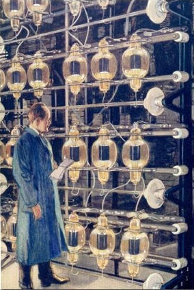 Early 1920s commercial transmitting tubes (valves) ganged together for very high power. These tubes operated at 10,000 volts or more of direct current. With the evolution of the vacuum tube transmitters, a very similar thing also was happening with radio receivers High vacuum, affordable and reliable triode (and later multi element) tubes (valves) greatly outperformed the old crystal detector receivers and the old crystal receivers were relegated to hobbyists. Just 10 years after 1914, Armstrong's Superheterodyne receiver (based on the very same principle almost all radios use today) hit the commercial market in the form of the famous RCA Radiola model AR812.  The 1924 RCA Radiola model AR812 superheterodyne receiver
Early
radio very quickly evolved into better and better forms as better and
better vacuum tubes were developed, but the old
spark gap transmitter and the crystal receiver still holds our
imagination and to this day, the crystal radio is still popular with
hobbyists. The spark gap transmitter, not so much and besides
it's illegal to pollute the airwaves with one, however the name
"sparks" still lives on in the nickname given to radiomen, even on Star
Trek.
 The badge still worn by US Navy
Radiomen
representing the sparks given
off by the early spark gap transmitters.
The
End
Having
arrived this far,
obviously you have a superior attention span and reading ability that
far exceeds that of the majority of web users. I highly value
the opinion of people such
as yourself, so I ask you to briefly
tell me:
Did
you enjoy this article
or were you disappointed?
If you have any detailed comments, questions, complaints or suggestions, I would be grateful if you would please Other links to my radio pages that you might enjoy: If you want to know how the radio waves from the early transmitters were detected, you might be interested in my essay on  The Coherer and other early radio detectors If you would like to know how this kind radio equipment was actually used, you might be interested in my essay on  Shackleton's Trans Antarctic Expedition's missing radio equipment If you are interested in learning a little more about basic radio theory, please checkout 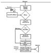 An essay on the Armstrong Superheterodyne Radio Principle If you want to learn something about how crystal radios work, please see the story of  My Heathkit CR-1 high performance crystal radio My Armstrong regenerative radio projects This is the story of my first regenerative radio I built when I was in the 8th grade, Over
50 years later, I built an almost identical radio, but using very cheap
and easily available components.
 An Armstrong "Crystal" Radio Amazing performance from a radio that is easier and cheaper to build than almost any crystal radio. If you want to build a simple radio yourself, this is the one I suggest. from "The Old Geezer Electrician" If you are looking to build something with the same great performance of these other regenerative radios, but looks a whole lot nicer, I would like to suggest  The Geezerola Senior radio Another Armstrong
regenerative radio story, but this one tunes shortwave,
 My Regenerative Shortwave Radio. If there is nothing on your local AM radio worth listening to, perhaps you would like to build A low power AM transmitter I have several other stories regarding antique and home made radios you might like to read.  Select Another Really Interesting Radio Story. |